Products
- Products
- Single wedge disc gate valve
- Double wedge disc gate valve
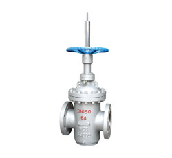
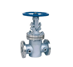
- Flat gate valve
- Parallel double gate valve
- Cryogenic gate valve
- Thermal insulation jacket gate valve
- High temperature high-pressure gate valve
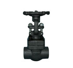
- Threaded and socket-welding gate valve
Contact us
Tel:+86-577-8682 5111
Email:zjbeize@163.com
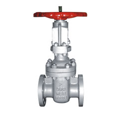
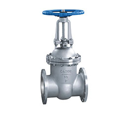
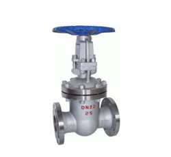
Z40H Wedge Elastic Single Gate Flange Gate Valve
Performance parameters
◎ Design standard: API 600, GB / T 12234
◎ Nominal diameter: DN50-800mm (2 "-24")
◎ Nominal pressure: PN16-PN250 (150LB-1500LB)
◎ Connection standard: ASME B16.5, ASME B16.47, ASME B16.25, GB / T9113
◎ Material range: carbon steel, alloy steel, stainless steel, low temperature steel
◎ Sealing material: stainless steel, hard alloy
◎ mode of operation: hand wheel, gear drive, electric, pneumatic
◎ Temperature range: -40 ~ 550 ℃
◎ Suitable medium: water, oil, gas, acid and other corrosive media
main feature
◎ compact structure, good rigidity, channel smooth
◎ Flow resistance coefficient is small
◎ anti-corrosion, wear resistance,
◎ Switching torque is small, long service life
◎ Clear rod bracket, bolt connection valve cover
◎ Large diameter roller bearings, fast closing flexible, easy opening and closing
Product appearance

Connection dimensions Z40H-16 DN50~600
| DN | L | D | D1 | D2 | f | b | Z-Φd | H | W |
WT Kg |
|
| RF | BW | ||||||||||
| 50 | 250 | 216 | 165 | 125 | 102 | 3 | 18 | 4-18 | 438 | 240 | 19 |
| 65 | 270 | 241 | 185 | 145 | 122 | 3 | 18 | 8-18 | 450 | 240 | 33 |
| 80 | 280 | 283 | 200 | 160 | 138 | 3 | 20 | 8-18 | 528 | 280 | 46 |
| 100 | 300 | 305 | 220 | 180 | 158 | 3 | 20 | 8-18 | 620 | 320 | 63 |
| 125 | 325 | 381 | 250 | 210 | 188 | 3 | 22 | 8-18 | 753 | 360 | 108 |
| 150 | 350 | 103 | 285 | 240 | 212 | 3 | 22 | 8-22 | 847 | 360 | 134 |
| 200 | 400 | 419 | 340 | 295 | 268 | 3 | 24 | 12-22 | 1039 | 400 | 192 |
| 250 | 450 | 457 | 405 | 355 | 320 | 3 | 26 | 12-26 | 1245 | 450 | 273 |
| 300 | 500 | 502 | 460 | 410 | 378 | 4 | 28 | 12-26 | 1472 | 560 | 379 |
| 350 | 550 | 572 | 520 | 470 | 438 | 4 | 30 | 16-26 | 1450 | 640 | 590 |
| 400 | 600 | 610 | 580 | 525 | 490 | 4 | 32 | 16-30 | 1887 | 640 | 850 |
| 450 | 650 | 660 | 640 | 585 | 550 | 4 | 40 | 20-30 | 2011 | 720 | 907 |
| 500 | 700 | 711 | 715 | 650 | 610 | 4 | 44 | 20-33 | 2181 | 720 | 958 |
| 600 | 800 | 813 | 840 | 770 | 725 | 5 | 54 | 20-36 | 2346 | 800 | 1112 |
Note: The above data for the conventional data, flange size in accordance with EN1092-1. If you have different needs, can be customized according to demand.
Connection dimensions Z40H-25 DN50~600
| DN | L | D | D1 | D2 | f | b | Z-Φd | H | W |
WT Kg |
|
| RF | BW | ||||||||||
| 50 | 250 | 216 | 165 | 125 | 102 | 3 | 20 | 4-18 | 438 | 240 | 28 |
| 65 | 270 | 241 | 185 | 145 | 122 | 3 | 22 | 8-18 | 450 | 240 | 33 |
| 80 | 280 | 283 | 200 | 160 | 138 | 3 | 24 | 8-18 | 528 | 280 | 46 |
| 100 | 300 | 305 | 235 | 190 | 162 | 3 | 24 | 8-22 | 620 | 320 | 64 |
| 125 | 325 | 381 | 270 | 220 | 188 | 3 | 26 | 8-26 | 753 | 360 | 116 |
| 150 | 350 | 406 | 300 | 250 | 218 | 3 | 28 | 8-26 | 847 | 360 | 141 |
| 200 | 400 | 419 | 360 | 310 | 278 | 3 | 30 | 8-26 | 1039 | 400 | 213 |
| 250 | 450 | 457 | 425 | 370 | 335 | 3 | 32 | 8-30 | 1245 | 450 | 290 |
| 300 | 500 | 502 | 485 | 430 | 395 | 4 | 34 | 12-30 | 1472 | 560 | 400 |
| 350 | 550 | 762 | 555 | 490 | 450 | 4 | 38 | 12-33 | 1450 | 640 | 631 |
| 400 | 600 | 838 | 620 | 550 | 505 | 4 | 40 | 12-36 | 1887 | 640 | 900 |
| 450 | 650 | 914 | 670 | 600 | 555 | 4 | 46 | 16-36 | 2011 | 720 | 1013 |
| 500 | 700 | 991 | 730 | 660 | 615 | 4 | 48 | 16-36 | 2181 | 720 | 1166 |
| 600 | 800 | 1143 | 845 | 770 | 720 | 5 | 58 | 16-39 | 2346 | 800 | 1258 |
Note: The above data for the conventional data, flange size in accordance with EN1092-1. If you have different needs, can be customized according to demand.
Connection dimensions Z40H-40 DN50~400
| DN | L | D | D1 | D2 | f | b | Z-Φd | H | W |
WT
Kg
|
|
| RF | BW | ||||||||||
| 50 | 250 | 216 | 165 | 125 | 102 | 3 | 20 | 4-18 | 440 | 280 | 29 |
| 65 | 280 | 241 | 185 | 145 | 122 | 3 | 22 | 8-18 | 473 | 280 | 39 |
| 80 | 310 | 283 | 200 | 160 | 138 | 3 | 24 | 8-18 | 552 | 320 | 52 |
| 100 | 350 | 305 | 235 | 190 | 162 | 3 | 24 | 8-22 | 671 | 360 | 80 |
| 125 | 400 | 381 | 270 | 220 | 188 | 3 | 26 | 8-26 | 726 | 400 | 127 |
| 150 | 450 | 406 | 300 | 250 | 218 | 3 | 28 | 8-26 | 883 | 400 | 145 |
| 200 | 550 | 419 | 375 | 320 | 285 | 3 | 34 | 12-30 | 1086 | 450 | 263 |
| 250 | 650 | 457 | 450 | 385 | 345 | 3 | 38 | 8-33 | 1298 | 560 | 368 |
| 300 | 750 | 502 | 515 | 450 | 310 | 4 | 42 | 12-33 | 1535 | 640 | 547 |
| 350 | 850 | 762 | 580 | 510 | 465 | 4 | 46 | 12-36 | 1678 | 640 | 679 |
| 400 | 950 | 838 | 660 | 585 | 535 | 4 | 50 | 12-39 | 1903 | 720 | 953 |
Note: The above data for the conventional data, flange size in accordance with EN1092-1. If you have different needs, can be customized according to demand.
Connection dimensions Z40H-63 DN50~300
| DN | L | D | D1 | D2 | f | b | Z-Φd | H | W |
WT Kg |
|
| RF | BW | ||||||||||
| 50 | 250 | 292 | 180 | 135 | 102 | 3 | 26 | 4-22 | 448 | 280 | 34 |
| 65 | 280 | 330 | 205 | 160 | 122 | 3 | 26 | 8-22 | 475 | 280 | 43 |
| 80 | 310 | 356 | 215 | 170 | 138 | 3 | 28 | 8-22 | 553 | 320 | 60 |
| 100 | 350 | 406 | 250 | 200 | 162 | 3 | 30 | 8-26 | 679 | 360 | 89 |
| 125 | 400 | 457 | 295 | 240 | 188 | 3 | 34 | 8-30 | 779 | 400 | 140 |
| 150 | 450 | 495 | 345 | 280 | 218 | 3 | 36 | 8-33 | 893 | 450 | 207 |
| 200 | 550 | 597 | 415 | 345 | 285 | 3 | 42 | 12-36 | 1100 | 560 | 325 |
| 250 | 650 | 673 | 470 | 400 | 345 | 3 | 46 | 8-36 | 1332 | 640 | 467 |
| 300 | 750 | 762 | 530 | 460 | 410 | 4 | 52 | 12-36 | 1535 | 640 | 590 |
Note: The above data for the conventional data, flange size in accordance with EN1092-1. If you have different needs, can be customized according to demand.
Connection dimensions Z40H-150 2"~36"
| NPS | DN | L | D | D1 | D2 | b | Z-Φd | H | W | |
| RF | BW | |||||||||
| 2 | 50 | 178 | 216 | 150 | 120.7 | 92 | 19.5 | 4-19 | 409 | 200 |
| 3 | 80 | 203 | 282 | 190 | 152.4 | 127 | 24.3 | 4-19 | 570 | 250 |
| 4 | 100 | 229 | 305 | 230 | 190.5 | 157.2 | 24.3 | 8-19 | 590 | 250 |
| 6 | 150 | 267 | 403 | 280 | 241.3 | 215.9 | 25.9 | 8-22 | 630 | 300 |
| 8 | 200 | 292 | 419 | 345 | 298.5 | 269.9 | 29 | 8-22 | 960 | 350 |
| 10 | 250 | 330 | 457 | 405 | 362 | 323.8 | 30.6 | 12-25 | 1158 | 400 |
| 12 | 300 | 356 | 502 | 485 | 431.8 | 381 | 32.2 | 12-25 | 1378 | 450 |
| 14 | 350 | 381 | 572 | 535 | 476.3 | 412.8 | 35.4 | 12-29 | 1543 | 500 |
| 16 | 400 | 406 | 610 | 595 | 539.8 | 469.9 | 37 | 16-29 | 1738 | 600 |
| 18 | 450 | 432 | 660 | 635 | 577.9 | 533.4 | 40.1 | 16-32 | 1959 | 600 |
| 20 | 500 | 457 | 711 | 700 | 635 | 584.2 | 43.3 | 20-32 | 2214 | 680 |
| 24 | 600 | 508 | 813 | 815 | 749.3 | 692.2 | 48.1 | 20-35 | 2599 | 760 |
| 30 | 750 | 610 | 914 | 985 | 914 | 857 | 74.5 | 28-35 | 3183 | 915 |
| 36 | 900 | 711 | 1016 | 1170 | 1086 | 1022 | 90.5 | 32-41 | 3737 | 915 |
Note: The above API6D standard design, flange size in accordance with ASME B16.5 / B16.47 standards. If you have different needs, can be customized according to demand.
Connection dimensions Z40H-300 2"~24"
| NPS | DN | L | D | D1 | D2 | b | Z-Φd | H | W | |
| RF | BW | |||||||||
| 2 | 50 | 216 | 216 | 165 | 127 | 92.1 | 22.7 | 8-19 | 424 | 200 |
| 3 | 80 | 282 | 282 | 210 | 168.3 | 127 | 29 | 8-22 | 535 | 250 |
| 4 | 100 | 305 | 305 | 255 | 200 | 157.2 | 32.2 | 8-22 | 615 | 250 |
| 6 | 150 | 403 | 403 | 320 | 269.9 | 215.9 | 37 | 12-22 | 795 | 350 |
| 8 | 200 | 419 | 419 | 380 | 330.2 | 269.9 | 41.7 | 12-25 | 1012 | 400 |
| 10 | 250 | 457 | 457 | 445 | 387.4 | 323.8 | 48.1 | 16-29 | 1231 | 450 |
| 12 | 300 | 502 | 505 | 520 | 450.8 | 381 | 51.3 | 16-32 | 1450 | 500 |
| 14 | 350 | 762 | 762 | 585 | 514.4 | 412.8 | 54.4 | 20-32 | 1645 | 600 |
| 16 | 400 | 838 | 838 | 650 | 571.5 | 469.9 | 57.6 | 20-35 | 1814 | 600 |
| 18 | 450 | 914 | 914 | 710 | 628.6 | 533.4 | 60.8 | 24-35 | 1943 | 680 |
| 20 | 500 | 991 | 991 | 775 | 685.8 | 584.2 | 64 | 24-35 | 2154 | 760 |
| 24 | 600 | 1143 | 1143 | 915 | 812.8 | 692.2 | 70.3 | 24-41 | 2553 | 915 |
Note: The above API6D standard design, flange size in accordance with ASME B16.5 standard. If you have different needs, can be customized according to demand.
Connection dimensions Z40H-600 2"~24"
| NPS | DN | L | D | D1 | D2 | b | Z-Φd | H | W | |
| RF | BW | |||||||||
| 2 | 50 | 292 | 292 | 165 | 127 | 92.1 | 32.4 | 8-19 | 458 | 250 |
| 3 | 80 | 356 | 356 | 210 | 168.3 | 127 | 38.8 | 8-22 | 570 | 250 |
| 4 | 100 | 432 | 432 | 275 | 215.9 | 157.2 | 45.1 | 8-25 | 390 | 350 |
| 6 | 150 | 559 | 559 | 355 | 292.1 | 215.9 | 54.7 | 12-29 | 910 | 450 |
| 8 | 200 | 660 | 660 | 420 | 349.2 | 269.9 | 62.6 | 12-32 | 1064 | 500 |
| 10 | 250 | 787 | 787 | 510 | 431.8 | 323.8 | 70.5 | 16-35 | 1257 | 600 |
| 12 | 300 | 838 | 838 | 560 | 489 | 381 | 73.7 | 20-35 | 1468 | 680 |
| 14 | 350 | 889 | 889 | 605 | 527 | 412.8 | 76.9 | 20-38 | 1623 | 760 |
| 16 | 400 | 991 | 991 | 685 | 603.2 | 469.9 | 83.2 | 20-41 | 1816 | 760 |
| 18 | 450 | 1092 | 1092 | 745 | 654 | 533.4 | 89.6 | 20-44 | 2100 | 915 |
| 20 | 500 | 1194 | 1194 | 815 | 723.9 | 584.2 | 95.9 | 24-44 | 2250 | 950 |
| 24 | 600 | 1397 | 1397 | 940 | 838.2 | 692.2 | 108.6 | 24-51 | 2370 | 1000 |
Note: The above API6D standard design, flange size in accordance with ASME B16.5 standard. If you have different needs, can be customized according to demand.
Connection dimensions Z40H-900 2"~8"
| NPS | DN | L | D | D1 | D2 | b | Z-Φd | H | W | |
| RF | BW | |||||||||
| 2 | 50 | 368 | 368 | 215 | 165.1 | 92.1 | 45.1 | 8-25 | 500 | 280 |
| 2 1/2 | 75 | 419 | 419 | 245 | 190.5 | 104.8 | 48.3 | 8-29 | 550 | 300 |
| 3 | 80 | 381 | 381 | 240 | 190.5 | 127 | 45.1 | 8-25 | 610 | 300 |
| 4 | 100 | 457 | 457 | 290 | 235 | 157.2 | 51.5 | 8-32 | 702 | 350 |
| 6 | 150 | 610 | 610 | 380 | 317.5 | 215.9 | 62.6 | 12-32 | 980 | 500 |
| 8 | 200 | 737 | 737 | 470 | 393.7 | 269.9 | 70.5 | 12-38 | 1100 | 600 |
Note: The above API6D standard design, flange size in accordance with ASME B16.5 standard. If you have different needs, can be customized according to demand.
Connection dimensions Z40H-1500 2"~8"
| NPS | DN | L | D | D1 | D2 | b | Z-Φd | H | W | |
| RF | BW | |||||||||
| 2 | 50 | 368 | 368 | 215 | 165.1 | 92.1 | 45.1 | 8-25 | 510 | 280 |
| 3 | 80 | 470 | 470 | 265 | 203.5 | 127 | 54.7 | 8-32 | / | / |
| 4 | 100 | 546 | 546 | 310 | 241.3 | 157.2 | 61 | 8-35 | / | / |
| 6 | 150 | 705 | 705 | 395 | 317.5 | 215.9 | 89.6 | 12-38 | / | / |
| 8 | 200 | 832 | 832 | 485 | 393.7 | 269.9 | 99.1 | 12-45 | / | / |
Z42H Wedge double gate flanged gate valve
Performance parameters
◎ Design standard: GB / T 12234, JB / T 3595
◎ Nominal diameter: DN100-300mm (4 "-12")
◎ Nominal pressure: PN16-PN100 (150LB-600LB)
◎ Connection standard: GB / T 9113, GB / T 79
◎ Material range: carbon steel, alloy steel, stainless steel, low temperature steel
◎ Sealing material: stainless steel, hard alloy
◎ mode of operation: hand wheel, gear drive, electric, pneumatic
◎ Temperature range: -196 ~ 650 ℃
◎ Suitable medium: water, oil, gas, acid and other corrosive media
main feature
◎ compact structure, good rigidity, channel smooth
◎ Flow resistance coefficient is small
◎ anti-corrosion, wear resistance,
◎ Switching torque is small, long service life
◎ Clear rod bracket, bolt connection valve cover
◎ medium flow is not restricted, not spoiler, do not reduce the pressure
◎ sealing surface by medium erosion small
Product appearance

Connection dimensions Z42H-100 DN100~300
| DN | L | D | D1 | D2 | b | f | Z-Φd | H | W |
WT Kg |
|
| RF | BW | ||||||||||
| 100 | 350 | 432 | 265 | 210 | 172 | 38 | 3 | 8-30 | 575 | 360 | 88 |
| 125 | 400 | 508 | 310 | 250 | 210 | 42 | 3 | 8-34 | 725 | 400 | 168 |
| 150 | 450 | 556 | 350 | 290 | 250 | 46 | 3 | 12-34 | 758 | 500 | 235 |
| 200 | 550 | 660 | 430 | 360 | 312 | 54 | 3 | 12-41 | 898 | 600 | 338 |
| 225 | 650 | / | 470 | 400 | 352 | 56 | 3 | 12-41 | 1028 | 600 | 521 |
| 250 | 650 | 787 | 500 | 430 | 382 | 60 | 3 | 12-41 | 1049 | 640 | 558 |
| 300 | 750 | 838 | 585 | 500 | 442 | 70 | 4 | 16-48 | 1208 | 640 | 686 |
Note: The above data for the conventional data, flange size in accordance with EN1092-1. If you have different needs, can be customized according to demand. PN16 ~ PN64 dimensions and flange dimensions, see Z40H wedge-type elastic single-plate flange valve
flat flange valve
Z43H flat flange valve
Performance parameters
◎ Design standard: GB / T 5298, API 6D
◎ Nominal diameter: DN50-1000mm (2 "-40")
◎ Nominal pressure: PN16-PN100 (150LB-600LB)
◎ Connection standard: GB / T 79, ASME B16.5
◎ Material range: carbon steel, alloy steel, stainless steel
◎ Sealing material: stainless steel, hard alloy
◎ mode of operation: hand wheel, gear drive, electric, pneumatic
◎ Temperature range: -29 ~ 425 ℃
◎ Suitable medium: water, oil, gas, acid and other corrosive media
main feature
◎ compact structure, good rigidity, channel smooth
◎ Flow resistance coefficient is small
◎ anti-corrosion, wear resistance,
◎ Switching torque is small, long service life
◎ nature of the fire design
Product appearance

Connection dimensions Z43H-16 DN50~1000
| DN | L | D | D1 | D2 | f | b | Z-Φd | H | H1 | W | WT | H | H1 | W | WT |
| No diversion hole (hand wheel) | Diversion holes (handwheel / gear / pneumatic / electric) | ||||||||||||||
| 50 | 178 | 165 | 125 | 102 | 3 | 18 | 4-18 | 450 | 80 | 250 | 25 | 584 | 80 | 250 | 27 |
| 65 | 190 | 185 | 145 | 122 | 3 | 18 | 8-18 | 550 | 95 | 300 | 42 | 634 | 95 | 250 | 46 |
| 80 | 203 | 200 | 160 | 138 | 3 | 20 | 8-18 | 610 | 100 | 300 | 48 | 688 | 100 | 250 | 52 |
| 100 | 229 | 220 | 180 | 158 | 3 | 20 | 8-18 | 700 | 114 | 300 | 55 | 863 | 114 | 300 | 60 |
| 125 | 254 | 250 | 210 | 188 | 3 | 22 | 8-18 | 798 | 132 | 350 | 100 | 940 | 132 | 350 | 110 |
| 150 | 267 | 285 | 240 | 212 | 3 | 22 | 8-22 | 895 | 150 | 350 | 115 | 1030 | 150 | 350 | 126 |
| 200 | 292 | 340 | 295 | 268 | 3 | 24 | 12-22 | 1130 | 188 | 350 | 150 | 1277 | 168 | 350 | 165 |
| 250 | 330 | 405 | 355 | 320 | 3 | 26 | 12-26 | 1290 | 225 | 400 | 260 | 1491 | 203 | 400 | 385 |
| 300 | 356 | 460 | 410 | 378 | 4 | 28 | 12-26 | 1480 | 247 | 450 | 350 | 1701 | 237 | 450 | 385 |
| 350 | 381 | 520 | 470 | 438 | 4 | 30 | 16-26 | 1660 | 275 | 450 | 500 | 1875 | 265 | 500 | 550 |
| 400 | 406 | 580 | 525 | 490 | 4 | 32 | 16-30 | 1850 | 312 | 500 | 610 | 2180 | 300 | 305 | 671 |
| 450 | 432 | 640 | 585 | 550 | 4 | 40 | 20-30 | 2080 | 335 | 500 | 970 | 2440 | 325 | 305 | 1069 |
| 500 | 457 | 715 | 650 | 610 | 4 | 44 | 20-33 | 2300 | 380 | 600 | 1200 | 2860 | 360 | 305 | 1320 |
| 600 | 508 | 840 | 770 | 725 | 5 | 54 | 20-36 | 2680 | 445 | 800 | 1850 | 3450 | 425 | 305 | 2035 |
| 700 | 610 | 910 | 840 | 795 | 5 | 40 | 24-36 | 3080 | 490 | 800 | 2910 | 3960 | 460 | 305 | 3201 |
| 800 | 660 | 1025 | 950 | 900 | 5 | 42 | 24-39 | 3491 | 560 | 1000 | 3600 | 4550 | 512 | 305 | 3960 |
| 900 | 711 | 1125 | 1050 | 1000 | 5 | 44 | 28-39 | 3897 | 610 | 1000 | 4950 | 5250 | 565 | 250 | 5445 |
| 1000 | 813 | 1255 | 1170 | 1115 | 5 | 46 | 28-42 | 4317 | 715 | 1200 | 6160 | 5870 | 630 | 250 | 6776 |
Note: The above data for the conventional data, flange size in accordance with EN1092-1. If you have different needs, can be customized according to demand.
Connection dimensions Z43H-25 DN50~1000
| DN | L | D | D1 | D2 | f | b | Z-Φd | H | H1 | W | WT | H | H1 | W | WT |
| No diversion hole (hand wheel) | Diversion holes (handwheel / gear / pneumatic / electric) | ||||||||||||||
| 50 | 178 | 165 | 125 | 102 | 3 | 20 | 4-18 | 450 | 80 | 250 | 25 | 584 | 80 | 250 | 27 |
| 65 | 190 | 185 | 145 | 122 | 3 | 22 | 8-18 | 550 | 95 | 300 | 45 | 634 | 95 | 300 | 49 |
| 80 | 203 | 200 | 160 | 138 | 3 | 24 | 8-18 | 610 | 100 | 300 | 50 | 688 | 100 | 350 | 55 |
| 100 | 229 | 235 | 190 | 162 | 3 | 24 | 8-22 | 700 | 114 | 300 | 60 | 863 | 114 | 350 | 66 |
| 125 | 254 | 270 | 220 | 188 | 3 | 26 | 8-26 | 798 | 132 | 350 | 110 | 940 | 132 | 350 | 121 |
| 150 | 267 | 300 | 250 | 218 | 3 | 28 | 8-26 | 895 | 150 | 350 | 128 | 1030 | 150 | 400 | 121 |
| 200 | 292 | 360 | 310 | 278 | 3 | 30 | 8-26 | 1130 | 190 | 350 | 228 | 1277 | 168 | 450 | 181 |
| 250 | 330 | 425 | 370 | 335 | 3 | 32 | 8-30 | 1290 | 225 | 400 | 280 | 1491 | 203 | 500 | 310 |
| 300 | 356 | 485 | 430 | 395 | 4 | 34 | 12-30 | 1480 | 250 | 450 | 370 | 1701 | 237 | 305 | 410 |
| 350 | 381 | 555 | 490 | 450 | 4 | 38 | 12-33 | 1660 | 275 | 450 | 525 | 1875 | 265 | 305 | 580 |
| 400 | 406 | 620 | 550 | 505 | 4 | 40 | 12-36 | 1850 | 312 | 500 | 635 | 2180 | 300 | 305 | 700 |
| 450 | 432 | 670 | 600 | 555 | 4 | 46 | 16-36 | 2080 | 335 | 500 | 1010 | 2440 | 325 | 305 | 1100 |
| 500 | 457 | 730 | 660 | 615 | 4 | 48 | 16-36 | 2300 | 380 | 600 | 1280 | 2860 | 360 | 305 | 1410 |
| 600 | 508 | 845 | 770 | 720 | 5 | 58 | 16-39 | 2680 | 445 | 800 | 1930 | 3450 | 425 | 305 | 2120 |
| 700 | 610 | 960 | 875 | 820 | 5 | 50 | 20-42 | 3080 | 490 | 800 | 3010 | 3960 | 460 | 305 | 3310 |
| 800 | 660 | 1085 | 990 | 930 | 5 | 54 | 20-48 | 3491 | 560 | 1000 | 3820 | 4550 | 512 | 305 | 4200 |
| 900 | 711 | 1185 | 1090 | 1030 | 5 | 58 | 24-48 | 3897 | 610 | 1000 | 5120 | 5250 | 595 | / | 5630 |
| 1000 | 813 | 1320 | 1210 | 1140 | 5 | 62 | 24-56 | 4317 | 715 | 1200 | 6400 | 5870 | 660 | / | 7040 |
Note: The above data for the conventional data, flange size in accordance with EN1092-1. If you have different needs, can be customized according to demand.
Connection dimensions Z43H-40 DN50~800
| DN | L | D | D1 | D2 | f | b | Z-Φd | H | H1 | W | WT | H | H1 | W | WT |
| No diversion hole (hand wheel) | Diversion holes (handwheel / gear / pneumatic / electric) | ||||||||||||||
| 50 | 216 | 165 | 125 | 102 | 3 | 20 | 4-18 | 458 | 80 | 250 | 38 | 584 | 80 | 250 | 42 |
| 65 | 241 | 185 | 145 | 122 | 3 | 22 | 8-18 | 555 | 95 | 300 | 57 | 634 | 95 | 250 | 62 |
| 80 | 283 | 200 | 160 | 138 | 3 | 24 | 8-18 | 615 | 100 | 300 | 68 | 679 | 102 | 250 | 75 |
| 100 | 305 | 235 | 190 | 162 | 3 | 24 | 8-22 | 710 | 111 | 300 | 78 | 863 | 115 | 300 | 82 |
| 125 | 381 | 270 | 220 | 188 | 3 | 26 | 8-26 | 796 | 132 | 350 | 133 | 940 | 133 | 350 | 146 |
| 150 | 403 | 300 | 250 | 218 | 3 | 28 | 8-26 | 900 | 150 | 350 | 165 | 1040 | 152 | 350 | 181 |
| 200 | 419 | 375 | 320 | 285 | 3 | 34 | 12-30 | 1135 | 188 | 350 | 315 | 1282 | 188 | 350 | 346 |
| 250 | 457 | 450 | 385 | 345 | 3 | 38 | 12-33 | 1401 | 225 | 400 | 410 | 1495 | 223 | 400 | 451 |
| 300 | 502 | 515 | 450 | 310 | 4 | 42 | 16-33 | 1580 | 247 | 450 | 620 | 1701 | 250 | 450 | 682 |
| 350 | 572 | 580 | 510 | 465 | 4 | 46 | 16-36 | / | / | / | / | 1880 | 280 | 500 | / |
| 400 | 610 | 660 | 585 | 535 | 4 | 50 | 16-39 | / | / | / | / | 2200 | 310 | 305 | / |
| 450 | 660 | 685 | 610 | 560 | 4 | 57 | 20-39 | / | / | / | / | 2480 | 335 | 305 | / |
| 500 | 711 | 755 | 670 | 615 | 4 | 57 | 20-42 | / | / | / | / | 2890 | 380 | 305 | / |
| 600 | 787 | 890 | 795 | 735 | 5 | 72 | 20-48 | / | / | / | / | 3480 | 450 | 305 | / |
Note: The above data for the conventional data, flange size in accordance with EN1092-1. If you have different needs, can be customized according to demand.
Connection dimensions Z43H-63 DN50~600
| DN | L | D | D1 | D2 | f | b | Z-Φd | H | H1 | W | WT | H | H1 | W | WT |
| No diversion hole (hand wheel) | Diversion holes (handwheel / gear / pneumatic / electric) | ||||||||||||||
| 50 | 250 | 180 | 135 | 102 | 3 | 26 | 4-22 | 460 | 108 | 300 | 55 | 584 | 90 | 250 | 50 |
| 65 | 290 | 205 | 160 | 122 | 3 | 26 | 8-22 | 555 | 125 | 300 | 72 | 634 | 105 | 250 | 79 |
| 80 | 310 | 215 | 170 | 138 | 3 | 28 | 8-22 | 625 | 146 | 350 | 85 | 679 | 110 | 250 | 93 |
| 100 | 350 | 250 | 200 | 162 | 3 | 30 | 8-26 | 720 | 165 | 350 | 98 | 763 | 130 | 300 | 108 |
| 125 | 400 | 295 | 240 | 188 | 3 | 34 | 8-30 | 806 | 190 | 400 | 164 | 970 | 150 | 300 | 180 |
| 150 | 450 | 345 | 280 | 218 | 3 | 36 | 8-33 | 910 | 220 | 400 | 205 | 1038 | 175 | 350 | 255 |
| 200 | 550 | 415 | 345 | 285 | 3 | 42 | 12-36 | 1145 | 280 | 500 | 350 | 1282 | 210 | 350 | 385 |
| 250 | 650 | 470 | 400 | 345 | 3 | 46 | 8-36 | 1411 | 330 | 500 | 490 | 1495 | 240 | 400 | 539 |
| 300 | 750 | 530 | 460 | 410 | 4 | 52 | 12-36 | 1590 | 380 | 600 | 760 | 1965 | 270 | 450 | 836 |
| 350 | 850 | 600 | 525 | 465 | 4 | 56 | 12-39 | / | / | / | / | 2185 | 300 | 500 | / |
| 400 | 950 | 670 | 585 | 535 | 4 | 60 | 12-42 | / | / | / | / | 2573 | 335 | 305 | / |
| 450 | 1050 | 800 | 705 | 615 | 4 | 68 | 16-48 | / | / | / | / | 2800 | 360 | 305 | / |
| 500 | 1150 | 800 | 705 | 615 | 4 | 68 | 16-48 | / | / | / | / | 3280 | 405 | 305 | / |
| 600 | 1350 | 930 | 820 | 735 | 5 | 76 | 16-56 | / | / | / | / | 3800 | 470 | 305 | / |
Note: The above data for the conventional data, flange size in accordance with EN1092-1. If you have different needs, can be customized according to demand
Connection dimensions Z43H-100 DN50~400
| DN | L | D | D1 | D2 | f | b | Z-Φd | H | H1 | W | WT | H | H1 | W | WT |
| No diversion hole (hand wheel) | Diversion holes (handwheel / gear / pneumatic / electric) | ||||||||||||||
| 50 | 250 | 195 | 145 | 102 | 3 | 30 | 4-26 | 468 | 108 | 300 | 65 | 590 | 100 | 250 | 65 |
| 65 | 280 | 220 | 170 | 122 | 3 | 34 | 8-26 | 565 | 125 | 300 | 93 | 640 | 115 | 250 | 93 |
| 80 | 310 | 230 | 180 | 138 | 3 | 36 | 8-26 | 625 | 145 | 350 | 110 | 680 | 120 | 250 | 108 |
| 100 | 350 | 265 | 210 | 162 | 3 | 40 | 8-30 | 720 | 165 | 350 | 134 | 870 | 135 | 300 | 134 |
| 125 | 400 | 315 | 250 | 188 | 3 | 40 | 8-33 | 806 | 190 | 400 | 203 | 980 | 155 | 350 | 203 |
| 150 | 450 | 355 | 290 | 218 | 3 | 44 | 8-33 | 910 | 220 | 400 | 320 | 1100 | 180 | 350 | 317 |
| 200 | 550 | 430 | 360 | 285 | 3 | 52 | 8-36 | 1145 | 280 | 500 | 545 | 1315 | 220 | 350 | 545 |
| 250 | 650 | 505 | 430 | 345 | 3 | 60 | 8-39 | 1411 | 330 | 500 | 630 | 1605 | 255 | 400 | 627 |
| 300 | 750 | 585 | 500 | 410 | 4 | 68 | 12-42 | 1590 | 380 | 600 | 870 | 1295 | 295 | 450 | 869 |
| 350 | 850 | 655 | 560 | 465 | 4 | 74 | 12-48 | / | / | / | / | 2280 | 335 | 500 | / |
| 400 | 950 | 715 | 620 | 535 | 4 | 78 | 12-48 | / | / | / | / | 2580 | 360 | 305 | / |
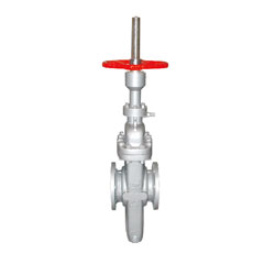
Parallel double plate gate valve
Z44H Parallel double plate flanged gate valve
Performance parameters
◎ Design standard: API, HG, GB
◎ Nominal diameter: DN50-500mm (2 "-25")
◎ Nominal pressure: PN16-PN40 (150LB-300LB)
◎ Connection standard: ASME B16.5, EN1092, ISO7005, GB / T9113,
◎ Material range: carbon steel, stainless steel
◎ Sealing material: stainless steel, hard alloy
◎ mode of operation: hand wheel, gear drive, electric, pneumatic
◎ Temperature range: -29 ~ 425 ℃
◎ Suitable medium: water, oil, gas and so on
main feature
◎ compact structure, good rigidity, channel smooth
◎ Flow resistance coefficient is small
◎ anti-corrosion, wear resistance,
◎ Switching torque is small, long service life
◎ nature of the fire design
Product appearance

Dimensions Z44H-16 DN50~800
| DN | NPS | L | D | H | H1(open) | W | WT(Kg) |
| 50 | 2 | 250 | 160 | 375 | 430 | 250 | 23 |
| 65 | 2 1/2 | 270 | 180 | 445 | 517 | 300 | 37 |
| 80 | 3 | 280 | 195 | 445 | 530 | 300 | 39 |
| 100 | 4 | 300 | 215 | 510 | 610 | 300 | 52 |
| 125 | 5 | 325 | 245 | 665 | 800 | 350 | 100 |
| 150 | 6 | 350 | 280 | 658 | 818 | 350 | 119 |
| 200 | 8 | 400 | 335 | 681 | 891 | 400 | 186 |
| 250 | 10 | 450 | 405 | 870 | 1130 | 450 | 263 |
| 300 | 12 | 500 | 480 | 870 | 1130 | 500 | 385 |
| 350 | 14 | 550 | 520 | 920 | 1280 | 550 | 514 |
| 400 | 16 | 600 | 580 | 920 | 1450 | 700 | 800 |
| 450 | 18 | 650 | 640 | 1040 | 1600 | 700 | 1060 |
| 500 | 20 | 700 | 705 | 1290 | 1800 | 700 | 1450 |
| 600 | 24 | 800 | 840 | 1490 | 2100 | 900 | 1750 |
| 700 | 28 | 900 | 910 | 2420 | 3130 | 900 | 2160 |
| 800 | 32 | 1000 | 1020 | 1890 | 2700 | 900 | 2470 |
Note: The size of the flange connection see the Z40H-16 wedge-type elastic single gate flange valve. Flange dimensions according to EN1092-1. If you have different needs, can be customized according to demand.
Dimensions Z44H-25 DN50~800
| DN | NPS | L | D | H | H1(open) | W | WT(Kg) |
| 50 | 2 | 250 | 160 | 390 | 430 | 250 | 24 |
| 65 | 2 1/2 | 270 | 180 | 445 | 517 | 300 | 37 |
| 80 | 3 | 280 | 195 | 450 | 530 | 300 | 38 |
| 100 | 4 | 300 | 230 | 510 | 620 | 300 | 58 |
| 125 | 5 | 325 | 270 | 665 | 800 | 350 | 100 |
| 150 | 6 | 350 | 300 | 685 | 818 | 350 | 119 |
| 200 | 8 | 400 | 360 | 690 | 891 | 400 | 197 |
| 250 | 10 | 450 | 425 | 870 | 1130 | 450 | 287 |
| 300 | 12 | 500 | 485 | 990 | 1300 | 500 | 385 |
| 350 | 14 | 550 | 550 | 920 | 1280 | 550 | 514 |
| 400 | 16 | 600 | 610 | 1040 | 1450 | 700 | 800 |
| 450 | 18 | 650 | 660 | 1140 | 1600 | 700 | 1060 |
| 500 | 20 | 700 | 730 | 1290 | 1800 | 700 | 1450 |
| 600 | 24 | 800 | 840 | 1490 | 2100 | 900 | 1750 |
| 700 | 28 | 900 | 995 | 1690 | 2400 | 900 | 2160 |
| 800 | 32 | 1000 | 1070 | 1890 | 2700 | 900 | 2470 |
Note: The size of the flange connection see Z40H-25 wedge-type flexible single-plate flange valve flange size in accordance with EN1092-1. If you have different needs, can be customized according to demand.
Dimensions Z44H-40 DN50~800
| DN | NPS | L | D | H | H1(open) | W | WT(Kg) |
| 50 | 2 | 250 | 160 | 395 | 450 | 250 | 30 |
| 65 | 2 1/2 | 290 | 180 | 458 | 530 | 300 | 43 |
| 80 | 3 | 310 | 195 | 477 | 565 | 300 | 62 |
| 100 | 4 | 350 | 230 | 530 | 640 | 300 | 82 |
| 125 | 5 | 400 | 270 | 605 | 740 | 350 | 115 |
| 150 | 6 | 450 | 300 | 725 | 885 | 350 | 145 |
| 200 | 8 | 550 | 375 | 905 | 1115 | 400 | 210 |
| 250 | 10 | 650 | 445 | 1035 | 1295 | 450 | 315 |
| 300 | 12 | 750 | 510 | 1135 | 1445 | 500 | 400 |
| 350 | 14 | 850 | 570 | 1220 | 1580 | 550 | 550 |
| 400 | 16 | 950 | 665 | 1340 | 1750 | 700 | 900 |
| 450 | 18 | 1050 | 680 | 1440 | 1900 | 700 | 1240 |
| 500 | 20 | 1150 | 755 | 1590 | 2100 | 700 | 1900 |
Note: The flange connection dimensions see the Z40H-40 wedge-type elastic single gate flange valve flange size in accordance with EN1092-1. If you have different needs, can be customized according to demand.
Dimensions Z44H-63 DN50~400
| DN | NPS | L | D | H | H1(open) | W | WT(Kg) |
| 50 | 2 | 250 | 175 | 395 | 450 | 250 | 42 |
| 65 | 2 1/2 | 280 | 200 | 458 | 530 | 300 | 55 |
| 80 | 3 | 310 | 210 | 477 | 565 | 300 | 80 |
| 100 | 4 | 350 | 250 | 530 | 640 | 300 | 120 |
| 125 | 5 | 400 | 295 | 605 | 740 | 350 | 170 |
| 150 | 6 | 450 | 340 | 720 | 885 | 350 | 245 |
| 200 | 8 | 550 | 405 | 925 | 1135 | 450 | 415 |
| 250 | 10 | 650 | 470 | 1075 | 1335 | 450 | 415 |
| 300 | 12 | 750 | 530 | 1135 | 1445 | 500 | 505 |
| 350 | 14 | 850 | 595 | 1220 | 1580 | 550 | 650 |
| 400 | 16 | 950 | 670 | 1340 | 1750 | 700 | 1200 |
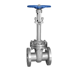
DZ41H Cryogenic Wedge Rigid Single Gate Flange Gate Valve
Performance parameters
◎ Design standard: API 600
◎ Nominal diameter: DN15-600mm (1/2 "-24")
◎ Nominal pressure: PN16-PN100 (150LB-900LB)
◎ Connection standard: ASME B16.5
◎ Material: low temperature steel, stainless steel
◎ Sealing material: stainless steel, hard alloy
◎ mode of operation: hand wheel, gear drive, electric, pneumatic
◎ Temperature range: -196 ~ 150 ℃
◎ Suitable medium: water, oil, gas and so on
main feature
◎ compact structure, good rigidity, channel smooth
◎ Flow resistance coefficient is small
◎ anti-corrosion, wear resistance,
◎ Switching torque is small, long service life
◎ nature of the fire design
Product appearance

Main profile and main connection dimensions
| model | temperature | -46℃ | -101℃ | -196℃ | |
| specification | size(mm) | ||||
| NPS | DN | Neck length H | |||
|
DZ40/DZ41H/ W/Y -150/ 300/600/900 |
1/2 | 15 | 90 | 110 | 130 |
| 3/4 | 20 | 100 | 110 | 140 | |
| 1 | 25 | 100 | 120 | 150 | |
| 11/4 | 32 | 110 | 130 | 160 | |
| 11/2 | 40 | 110 | 130 | 160 | |
| 2 | 50 | 110 | 130 | 170 | |
| 2 1/2 | 65 | 110 | 130 | 170 | |
| 3 | 80 | 120 | 150 | 190 | |
| 4 | 100 | 130 | 160 | 200 | |
| 5 | 125 | 130 | 160 | 200 | |
| 6 | 150 | 140 | 170 | 220 | |
| 8 | 200 | 140 | 170 | 220 | |
| 10 | 250 | 150 | 180 | 240 | |
| 12 | 300 | 150 | 180 | 240 | |
| 14 | 350 | 160 | 190 | 250 | |
| 16 | 400 | 160 | 190 | 250 | |
| 18 | 450 | 160 | 190 | 250 | |
| 20 | 500 | 170 | 200 | 260 | |
| 24 | 600 | 170 | 200 | 260 | |
Flange dimensions according to ASME B16.5. If you have different needs, can be customized according to demand.
Connection dimensions Z40H-150 2"~36"
| NPS | DN | L | D | D1 | D2 | b | Z-Φd | H | W | |
| RF | BW | |||||||||
| 2 | 50 | 178 | 216 | 150 | 120.7 | 92 | 19.5 | 4-19 | 409 | 200 |
| 3 | 80 | 203 | 282 | 190 | 152.4 | 127 | 24.3 | 4-19 | 570 | 250 |
| 4 | 100 | 229 | 305 | 230 | 190.5 | 157.2 | 24.3 | 8-19 | 590 | 250 |
| 6 | 150 | 267 | 403 | 280 | 241.3 | 215.9 | 25.9 | 8-22 | 630 | 300 |
| 8 | 200 | 292 | 419 | 345 | 298.5 | 269.9 | 29 | 8-22 | 960 | 350 |
| 10 | 250 | 330 | 457 | 405 | 362 | 323.8 | 30.6 | 12-25 | 1158 | 400 |
| 12 | 300 | 356 | 502 | 485 | 431.8 | 381 | 32.2 | 12-25 | 1378 | 450 |
| 14 | 350 | 381 | 572 | 535 | 476.3 | 412.8 | 35.4 | 12-29 | 1543 | 500 |
| 16 | 400 | 406 | 610 | 595 | 539.8 | 469.9 | 37 | 16-29 | 1738 | 600 |
| 18 | 450 | 432 | 660 | 635 | 577.9 | 533.4 | 40.1 | 16-32 | 1959 | 600 |
| 20 | 500 | 457 | 711 | 700 | 635 | 584.2 | 43.3 | 20-32 | 2214 | 680 |
| 24 | 600 | 508 | 813 | 815 | 749.3 | 692.2 | 48.1 | 20-35 | 2599 | 760 |
| 30 | 750 | 610 | 914 | 985 | 914 | 857 | 74.5 | 28-35 | 3183 | 915 |
| 36 | 900 | 711 | 1016 | 1170 | 1086 | 1022 | 90.5 | 32-41 | 3737 | 915 |
Note: The above API6D standard design, flange size in accordance with ASME B16.5 / B16.47 standards. If you have different needs, can be customized according to demand.
Connection dimensions Z40H-300 2"~24"
| NPS | DN | L | D | D1 | D2 | b | Z-Φd | H | W | |
| RF | BW | |||||||||
| 2 | 50 | 216 | 216 | 165 | 127 | 92.1 | 22.7 | 8-19 | 424 | 200 |
| 3 | 80 | 282 | 282 | 210 | 168.3 | 127 | 29 | 8-22 | 535 | 250 |
| 4 | 100 | 305 | 305 | 255 | 200 | 157.2 | 32.2 | 8-22 | 615 | 250 |
| 6 | 150 | 403 | 403 | 320 | 269.9 | 215.9 | 37 | 12-22 | 795 | 350 |
| 8 | 200 | 419 | 419 | 380 | 330.2 | 269.9 | 41.7 | 12-25 | 1012 | 400 |
| 10 | 250 | 457 | 457 | 445 | 387.4 | 323.8 | 48.1 | 16-29 | 1231 | 450 |
| 12 | 300 | 502 | 505 | 520 | 450.8 | 381 | 51.3 | 16-32 | 1450 | 500 |
| 14 | 350 | 762 | 762 | 585 | 514.4 | 412.8 | 54.4 | 20-32 | 1645 | 600 |
| 16 | 400 | 838 | 838 | 650 | 571.5 | 469.9 | 57.6 | 20-35 | 1814 | 600 |
| 18 | 450 | 914 | 914 | 710 | 628.6 | 533.4 | 60.8 | 24-35 | 1943 | 680 |
| 20 | 500 | 991 | 991 | 775 | 685.8 | 584.2 | 64 | 24-35 | 2154 | 760 |
| 24 | 600 | 1143 | 1143 | 915 | 812.8 | 692.2 | 70.3 | 24-41 | 2553 | 915 |
Note: The above API6D standard design, flange size in accordance with ASME B16.5 standard. If you have different needs, can be customized according to demand.
Connection dimensions Z40H-600 2"~24"
| NPS | DN | L | D | D1 | D2 | b | Z-Φd | H | W | |
| RF | BW | |||||||||
| 2 | 50 | 292 | 292 | 165 | 127 | 92.1 | 32.4 | 8-19 | 458 | 250 |
| 3 | 80 | 356 | 356 | 210 | 168.3 | 127 | 38.8 | 8-22 | 570 | 250 |
| 4 | 100 | 432 | 432 | 275 | 215.9 | 157.2 | 45.1 | 8-25 | 390 | 350 |
| 6 | 150 | 559 | 559 | 355 | 292.1 | 215.9 | 54.7 | 12-29 | 910 | 450 |
| 8 | 200 | 660 | 660 | 420 | 349.2 | 269.9 | 62.6 | 12-32 | 1064 | 500 |
| 10 | 250 | 787 | 787 | 510 | 431.8 | 323.8 | 70.5 | 16-35 | 1257 | 600 |
| 12 | 300 | 838 | 838 | 560 | 489 | 381 | 73.7 | 20-35 | 1468 | 680 |
| 14 | 350 | 889 | 889 | 605 | 527 | 412.8 | 76.9 | 20-38 | 1623 | 760 |
| 16 | 400 | 991 | 991 | 685 | 603.2 | 469.9 | 83.2 | 20-41 | 1816 | 760 |
| 18 | 450 | 1092 | 1092 | 745 | 654 | 533.4 | 89.6 | 20-44 | 2100 | 915 |
| 20 | 500 | 1194 | 1194 | 815 | 723.9 | 584.2 | 95.9 | 24-44 | 2250 | 950 |
| 24 | 600 | 1397 | 1397 | 940 | 838.2 | 692.2 | 108.6 | 24-51 | 2370 | 1000 |
Note: The above API6D standard design, flange size in accordance with ASME B16.5 standard. If you have different needs, can be customized according to demand.
Connection dimensions Z40H-900 2"~8"
| NPS | DN | L | D | D1 | D2 | b | Z-Φd | H | W | |
| RF | BW | |||||||||
| 2 | 50 | 368 | 368 | 215 | 165.1 | 92.1 | 45.1 | 8-25 | 500 | 280 |
| 2 1/2 | 75 | 419 | 419 | 245 | 190.5 | 104.8 | 48.3 | 8-29 | 550 | 300 |
| 3 | 80 | 381 | 381 | 240 | 190.5 | 127 | 45.1 | 8-25 | 610 | 300 |
| 4 | 100 | 457 | 457 | 290 | 235 | 157.2 | 51.5 | 8-32 | 702 | 350 |
| 6 | 150 | 610 | 610 | 380 | 317.5 | 215.9 | 62.6 | 12-32 | 980 | 500 |
| 8 | 200 | 737 | 737 | 470 | 393.7 | 269.9 | 70.5 | 12-38 | 1100 | 600 |
Note: The above API6D standard design, flange size in accordance with ASME B16.5 standard. If you have different needs, can be customized according to demand.
Connection dimensions Z40H-1500 2"~8"
| NPS | DN | L | D | D1 | D2 | b | Z-Φd | H | W | |
| RF | BW | |||||||||
| 2 | 50 | 368 | 368 | 215 | 165.1 | 92.1 | 45.1 | 8-25 | 510 | 280 |
| 3 | 80 | 470 | 470 | 265 | 203.5 | 127 | 54.7 | 8-32 | / | / |
| 4 | 100 | 546 | 546 | 310 | 241.3 | 157.2 | 61 | 8-35 | / | / |
| 6 | 150 | 705 | 705 | 395 | 317.5 | 215.9 | 89.6 | 12-38 | / | / |
| 8 | 200 | 832 | 832 | 485 | 393.7 | 269.9 | 99.1 | 12-45 | / | / |
Note: The above API6D standard design, flange size in accordance with ASME B16.5 standard. If you have different needs, can be customized according to demand.
BZ40H Thermal insulation wedge elastic single gate flanged gate valve
Performance parameters
◎ Design standard: GB / T 12234, API 600
◎ Nominal diameter: DN15-300mm (1/2 "-12")
◎ Nominal pressure: PN10-PN100 (150LB-600LB)
◎ Connection standard: GB / T9113, JB / T 74, ASME B16.5, SH 3006, HG 20615
◎ Material range: carbon steel, alloy steel, stainless steel
◎ Sealing material: stainless steel, hard alloy
◎ mode of operation: hand wheel, gear drive, electric, pneumatic
◎ Temperature range: -40 ~ 500 ℃
◎ Suitable medium: water, oil, gas, acid and other corrosive media
main feature
◎ compact structure, good rigidity, channel smooth
◎ Flow resistance coefficient is small
◎ anti-corrosion, wear resistance,
◎ Switching torque is small, long service life
◎ Clear rod bracket, bolt connection valve cover
◎ Jacket welding between the two flanges of the valve, the side of the valve, the bottom of the jacket is set to connect the mouth
◎ connection flange size than the same specifications of the ordinary valve flange connection large one to two specifications,
Structural length and the same specifications of the same general valve.
◎ jacket can be free to flow through the steam or other thermal insulation medium to ensure that the viscous medium can flow smoothly
Product appearance

Dimensions BZ40/Z41H-16 DN50~300
| DN | 50 | 65 | 80 | 100 | 125 | 150 | 200 | 250 | 300 |
| L | 250 | 265 | 280 | 300 | 325 | 3550 | 400 | 450 | 500 |
| H | 358 | 373 | 435 | 500 | 614 | 674 | 818 | 969 | 1145 |
| W | 240 | 240 | 280 | 300 | 320 | 360 | 400 | 450 | 560 |
Flange dimensions according to EN1092-1. If you have different needs, can be customized according to demand.
Connection dimensions BZ40/Z41H-16 DN50~600
| DN | L | D | D1 | D2 | f | b | Z-Φd | H | W |
WT Kg |
|
| RF | BW | ||||||||||
| 50 | 250 | 216 | 165 | 125 | 102 | 3 | 18 | 4-18 | 438 | 240 | 19 |
| 65 | 270 | 241 | 185 | 145 | 122 | 3 | 18 | 8-18 | 450 | 240 | 33 |
| 80 | 280 | 283 | 200 | 160 | 138 | 3 | 20 | 8-18 | 528 | 280 | 46 |
| 100 | 300 | 305 | 220 | 180 | 158 | 3 | 20 | 8-18 | 620 | 320 | 63 |
| 125 | 325 | 381 | 250 | 210 | 188 | 3 | 22 | 8-18 | 753 | 360 | 108 |
| 150 | 350 | 103 | 285 | 240 | 212 | 3 | 22 | 8-22 | 847 | 360 | 134 |
| 200 | 400 | 419 | 340 | 295 | 268 | 3 | 24 | 12-22 | 1039 | 400 | 192 |
| 250 | 450 | 457 | 405 | 355 | 320 | 3 | 26 | 12-26 | 1245 | 450 | 273 |
| 300 | 500 | 502 | 460 | 410 | 378 | 4 | 28 | 12-26 | 1472 | 560 | 379 |
| 350 | 550 | 572 | 520 | 470 | 438 | 4 | 30 | 16-26 | 1450 | 640 | 590 |
| 400 | 600 | 610 | 580 | 525 | 490 | 4 | 32 | 16-30 | 1887 | 640 | 850 |
| 450 | 650 | 660 | 640 | 585 | 550 | 4 | 40 | 20-30 | 2011 | 720 | 907 |
| 500 | 700 | 711 | 715 | 650 | 610 | 4 | 44 | 20-33 | 2181 | 720 | 958 |
| 600 | 800 | 813 | 840 | 770 | 725 | 5 | 54 | 20-36 | 2346 | 800 | 1112 |
Note: The above data for the conventional data, flange size in accordance with EN1092-1. If you have different needs, can be customized according to demand.
Dimensions BZ40/Z41H-25 DN50~300
| DN | 50 | 65 | 80 | 100 | 125 | 150 | 200 | 250 | 300 |
| L | 250 | 265 | 280 | 300 | 325 | 3550 | 400 | 450 | 500 |
| H | 358 | 373 | 435 | 500 | 614 | 674 | 818 | 969 | 1145 |
| W | 240 | 280 | 300 | 320 | 360 | 400 | 450 | 560 | 640 |
Flange dimensions according to EN1092-1. If you have different needs, can be customized according to demand.
Connection dimensions BZ40/Z41H-25 DN50~600
| DN | L | D | D1 | D2 | f | b | Z-Φd | H | W |
WT Kg |
|
| RF | BW | ||||||||||
| 50 | 250 | 216 | 165 | 125 | 102 | 3 | 20 | 4-18 | 438 | 240 | 28 |
| 65 | 270 | 241 | 185 | 145 | 122 | 3 | 22 | 8-18 | 450 | 240 | 33 |
| 80 | 280 | 283 | 200 | 160 | 138 | 3 | 24 | 8-18 | 528 | 280 | 46 |
| 100 | 300 | 305 | 235 | 190 | 162 | 3 | 24 | 8-22 | 620 | 320 | 64 |
| 125 | 325 | 381 | 270 | 220 | 188 | 3 | 26 | 8-26 | 753 | 360 | 116 |
| 150 | 350 | 406 | 300 | 250 | 218 | 3 | 28 | 8-26 | 847 | 360 | 141 |
| 200 | 400 | 419 | 360 | 310 | 278 | 3 | 30 | 8-26 | 1039 | 400 | 213 |
| 250 | 450 | 457 | 425 | 370 | 335 | 3 | 32 | 8-30 | 1245 | 450 | 290 |
| 300 | 500 | 502 | 485 | 430 | 395 | 4 | 34 | 12-30 | 1472 | 560 | 400 |
| 350 | 550 | 762 | 555 | 490 | 450 | 4 | 38 | 12-33 | 1450 | 640 | 631 |
| 400 | 600 | 838 | 620 | 550 | 505 | 4 | 40 | 12-36 | 1887 | 640 | 900 |
| 450 | 650 | 914 | 670 | 600 | 555 | 4 | 46 | 16-36 | 2011 | 720 | 1013 |
| 500 | 700 | 991 | 730 | 660 | 615 | 4 | 48 | 16-36 | 2181 | 720 | 1166 |
| 600 | 800 | 1143 | 845 | 770 | 720 | 5 | 58 | 16-39 | 2346 | 800 | 1258 |
Note: The above data for the conventional data, flange size in accordance with EN1092-1. If you have different needs, can be customized according to demand.
High temperature high-pressure gate valve
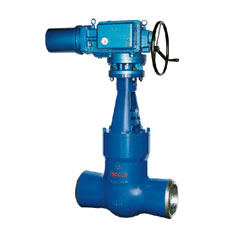
Z60Y Wedge elastic single gate welding valve
Performance parameters
◎ Design standards: ANSI B16.34, JIS L1 E101, JB / T 3595, DL / T 531
◎ Nominal diameter: DN50-400mm (2 "-16")
◎ Nominal pressure: PN16-PN420 (150LB-2500LB)
◎ Connection standard: ASME B16. 25, GB 12224
◎ Material range: high temperature steel, stainless steel
◎ Sealing material: cemented carbide
◎ mode of operation: hand wheel, gear drive, electric, pneumatic
◎ Temperature range: -29 ~ 570 ℃
◎ Applicable medium: high temperature water, superheated steam
main feature
◎ compact, rigid, good manufacturing process, a wide range of applications
◎ high temperature, high pressure, wear-resistant,
◎ smooth channel, the flow resistance is small,
◎ difficult to produce water hammer
◎ opening and closing more effort, light and flexible operation
Product appearance

Connection dimensions Z60/Z61-1500 2 1/2"~22"
| DN | NPS | L | D | H | W | WT(Kg) |
| 65 | 2 1/2 | 254 | 56 | 640 | 200 | 48 |
| 80 | 3 | 305 | 66 | 670 | 200 | 58 |
| 100 | 4 | 405 | 86 | 775 | 230 | 97 |
| 125 | 5 | 483 | 108 | 875 | 260 | 126 |
| 150 | 6 | 559 | 128 | 1055 | 360 | 212 |
| 200 | 8 | 711 | 170 | 1090 | 410 | 377 |
| 225 | 10 | 864 | 210 | 1445 | / | 687 |
| 300 | 12 | 991 | 250 | 1660 | / | 1043 |
| 350 | 14 | 1067 | 284 | 1810 | / | 1371 |
| 400 | 16 | 1194 | 324 | 1965 | / | 1773 |
| 450 | 18 | 1346 | 366 | 1570 | / | 2385 |
| 500 | 20 | 1473 | 408 | 2450 | / | 3187 |
| 550 | 22 | 1600 | 450 | 2700 | / | 4010 |
Note: The above API standard design, flange size in accordance with ASME B16.5 standard. If you have different needs, can be customized according to demand. DN65-DN200 for the hand wheel drive, DN225-DN550 gearbox drive
Connection dimensions Z60/Z61-2500 2 1/2"~16"
| DN | NPS | L | D | H | W | Kg |
| 65 | 2 1/2 | 330 | 46 | 635 | 20 | 70 |
| 80 | 3 | 368 | 54 | 680 | 230 | 90 |
| 100 | 4 | 457 | 72 | 805 | 260 | 142 |
| 125 | 5 | 533 | 88 | 965 | 360 | 222 |
| 150 | 6 | 610 | 106 | 1080 | 410 | 339 |
| 200 | 8 | 762 | 142 | 1205 | / | 648 |
| 250 | 10 | 914 | 176 | 1465 | / | 1086 |
| 300 | 12 | 1041 | 210 | 1715 | / | 1488 |
| 350 | 14 | 1118 | 236 | 1755 | / | 1787 |
| 400 | 16 | 1245 | 270 | 1955 | / | 2428 |
Note: The above API standard design, flange size in accordance with ASME B16.5 standard. If you have different needs, can be customized according to demand. DN65-DN150 for the hand wheel drive, DN200-DN400 for the gear box drive
Z11H Internal thread gate valve
Performance parameters
◎ Design standards: ANSI B16.34, API 600, API 602
◎ Nominal diameter: DN15-50mm (1/4 "-2")
◎ Nominal pressure: PN16-PN160 (150LB-900LB)
◎ Connection standard: ANSI B2.1, ANSI B16.11, ANSI B16.25
◎ Material range: carbon steel, alloy steel, stainless steel
◎ Sealing material: stainless steel, hard alloy
◎ Operation: handle operation
◎ Temperature range: -29 ~ 425 ℃
◎ Suitable medium: water, oil, gas, acid and other corrosive media
main feature
◎ compact structure, light weight, low flow resistance
◎ small opening and closing torque, excellent sealing performance
◎ There are integral type, two-piece type and three-piece type, which is convenient for maintenance and replacement
Product appearance

Connection dimensions Z11H-150 1/4"~2"
| NPS | L | L1 | H | W | WT Socket | WT Thread |
| 1/4 | / | 79 | 169 | 100 | / | 2.2 |
| 3/8 | / | 79 | 169 | 100 | / | 2.4 |
| 1/2 | 108 | 79 | 169 | 100 | 5 | 2.4 |
| 3/4 | 117 | 92 | 193 | 100 | 6.1 | 2.4 |
| 1 | 127 | 111 | 230 | 125 | 8.4 | 4.8 |
| 11/4 | 140 | 120 | 246 | 160 | 14.3 | 6.1 |
| 11/2 | 165 | 120 | 283 | 160 | 15.4 | 7.2 |
| 2 | 178 | 140 | 330 | 180 | 22.7 | 11.2 |
Note: The above API602 standard design, connection size in accordance with ASME standards. If you have different needs, can be customized according to demand.
Connection dimensions Z11H-300 1/4"~2"
| NPS | L | L1 | H | W | WT Socket | WT Thread |
| 1/4 | / | 79 | 169 | 100 | / | 2.2 |
| 3/8 | / | 79 | 169 | 100 | / | 2.4 |
| 1/2 | 140 | 79 | 169 | 100 | 5.2 | 2.4 |
| 3/4 | 152 | 92 | 193 | 100 | 6.3 | 2.4 |
| 1 | 165 | 111 | 230 | 125 | 8.6 | 4.8 |
| 11/4 | 178 | 120 | 246 | 160 | 14.5 | 6.1 |
| 11/2 | 190 | 120 | 283 | 160 | 15.6 | 7.2 |
| 2 | 216 | 140 | 330 | 180 | 22.8 | 11.2 |
Note: The above API602 standard design, connection size in accordance with ASME standards. If you have different needs, can be customized according to demand.
Connection dimensions Z11H-600 1/4"~2"
| NPS | L | L1 | H | W | WT Socket | WT Thread |
| 1/4 | / | 79 | 169 | 100 | / | 2.2 |
| 3/8 | / | 79 | 169 | 100 | / | 2.4 |
| 1/2 | 165 | 79 | 169 | 100 | 5.9 | 2.4 |
| 3/4 | 190 | 92 | 193 | 100 | 7.5 | 2.4 |
| 1 | 216 | 111 | 230 | 125 | 10.2 | 4.8 |
| 11/4 | 229 | 120 | 246 | 160 | 16.7 | 6.1 |
| 11/2 | 241 | 120 | 283 | 160 | 17.4 | 7.2 |
| 2 | 292 | 140 | 330 | 180 | 28.7 | 11.2 |
Note: The above API602 standard design, connection size in accordance with ASME standards. If you have different needs, can be customized according to demand.
Connection dimensions Z11H-800 1/4"~2"
| NPS | L | L1 | H | W | WT Socket | WT Thread |
| 1/4 | / | 79 | 169 | 100 | / | 2.2 |
| 3/8 | / | 79 | 169 | 100 | / | 2.4 |
| 1/2 | / | 79 | 169 | 100 | / | 2.4 |
| 3/4 | / | 92 | 193 | 100 | / | 2.4 |
| 1 | / | 111 | 230 | 125 | / | 4.8 |
| 11/4 | / | 120 | 246 | 160 | / | 6 |
| 11/2 | / | 120 | 283 | 160 | / | / |
| 2 | / | 120 | 283 | 160 | / | / |