Products
- Products
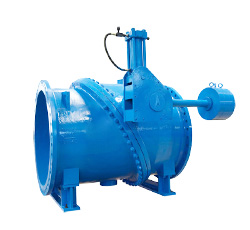
- Hydraulic control check valve
- Tilting disc check valve
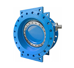
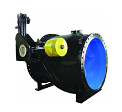
- Butterfly type check valve
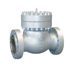
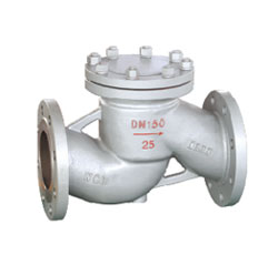
- Swing check valve
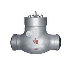
- Lift check valve
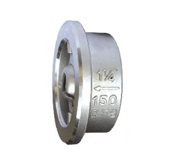
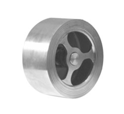
- Vertical wafer check valves
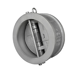
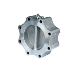
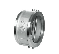
- Double disc check valve
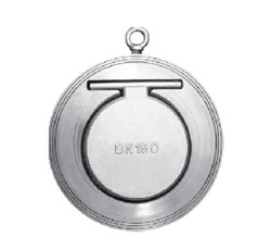
- Wafer single swing check valve
Contact us
Tel:+86-577-8682 5111
Email:zjbeize@163.com


Usage overview
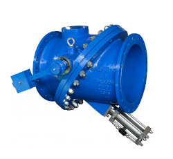
Heavy hammer hydraulic control check valve Applicable to the medium of water pipeline system pump outlet pipe, can play cut-off and check valve two functions. The valve closed back, you can control the closing time and speed, so as to eliminate or reduce the water hammer, to prevent the media back to the purpose of protecting the pipeline system.
Features Benefits
1、HD (H) 743X, HD (H) 7s43X, HD (H) 7BT43X type hydraulic checkback butterfly valve is opened by hydraulic drive, closed by heavy hammer potential, flexible and reliable.
2、The valve installed in the pump, can replace the valve (butterfly valve) and check valve two valves. And flow resistance coefficient is only 30% of the two flow resistance coefficient. Therefore, such valves for energy-saving products.
3、When the valve is closed, the liquid control device is divided into two stages: fast closing and slow closing. The first 60 ° is fast closing, and the latter 30 ° is slow closing. According to the working conditions, the liquid level of the control unit is set as follows: HD (H) 743X, HD (H) 7s43X, Different, fast and slow to adjust the time off and speed off two-stage angle to prevent the occurrence of a larger water hammer.
4、The three types of valves in the power failure, can be manually operated.
5、HD (H) 743X type also automatic reset function, when the valve opening to reduce (hammer drop) 15 °, the pump starts, automatically reset.
6、HD (H) 7s43X type has the following characteristics:
A: The valve has a heavy hammer locking device. When the valve opens in place, the heavy hammer arm locking pin to avoid for some reason heavy hammer down, so that the valve is closed, the hydraulic system with accumulator, to ensure that at any time to dial off valve.
B:The valve is equipped with a pressure relay system to ensure that the pressure required for the hydraulic system pressure.
7、HD (H) 7BT43X type has the following characteristics:
A:Butterfly valve off fast closing, slow off two stages and the time and angle are adjustable. Start off for the fast off angle adjustable between 60 ° ~ 80 °, time adjustable from 5 to 20 seconds. And then slow off the angle between 30 ° ~ 10 ° adjustable time adjustable between 10 to 50 seconds
B:With the role of holding pressure: the butterfly valve with hydraulic accumulator system, storage pressure oil, to add the system of leakage, and automatic pressure.
C: backup reset device: the butterfly valve is opened, when the hydraulic system in the trace of the internal leakage accumulator added, the pressure dropped to a certain value, the relay issued a make-up pressure to prevent the failure of the relay pressure, with trip switch reset device, That is, in the valve opening position of holding pressure and double-bit protection.
Model preparation

Implementation of standards
| Design and manufacturing basis | GB、JB | AWWA |
| Design and manufacturing standards |
B/T5299-1998 GB/T12238-2008 JB/T8527-1997 |
AWWA C504 |
| Flange connection standard |
GB/T9113.1-2000 GB/T17241.6-1998 |
AWWA C207 |
| Structure length standard | GB/T12221-2005 | AWWA C504 |
| Testing standard | GB/T13927-1992 | AWWA C504 |
Performance specification
| Nominal diameter (mm) | 1200-3400 | 500-2600 | 500-2000 | 500-1600 | 20"-144" | 16"-80" | ||||||||
| Nominal pressure (MPa) | 0.25 | 0.6 | 1.0 | 1.6 | 86psi | 150psi | ||||||||
|
Shell strength test(MPa) |
0.375 | 0.9 | 1.5 | 2.4 | 129psi | 225psi | ||||||||
|
Seal strength test(MPa) |
0.275 | 0.66 | 1.1 | 1.76 | 95psi | 165psi | ||||||||
| Gas seal test(MPa) | 0.6 | 0.6 | 0.6 | 0.6 | 0.6 | |||||||||
| Leakage rate | <0.1xDNmm3/s(Standards compliant GB/T13927-92) | Standards compliant AWWA C504 | ||||||||||||
| proper temperature |
|
|||||||||||||
| Applicable media | Fresh water, seawater, sewage and so on | |||||||||||||
| Drive mode | Hydraulic open, heavy hammer to help off | |||||||||||||
Material of parts
| Serial number | Main parts names | material |
| 1 | Bottom cover | Carbon steel, stainless steel |
| 2 | Valve shaft | 2Cr13、304、316、316L、F316、17-4PH etc. |
| 3 | Butterfly plate | Cast iron, carbon steel, alloy steel, stainless steel |
| 4 | Valve | Cast iron, carbon steel, alloy steel, stainless steel |
| 5 | Pin | 2Cr13、304、316、316L、F316、17-4PH etc. |
| 6 | Packing gland | Ductile iron, carbon steel, stainless steel, aluminum bronze |
| 7 | Stent | Cast iron, cast steel |
| 8 | Hydraulic device | Carbon steel etc. |
| 9 | Cylinder | Component |
| 10 | Pressure ring | Carbon steel, stainless steel |
| 11 | Screws | Carbon steel, stainless steel |
| 12 | Butterfly plate sealing ring | Multi-level sealing ring (stainless steel + graphite, asbestos board, PTFE), rubber |
| 13 | Body Seal Seat | Stainless steel body or surfacing stainless steel, carbide or inlaid stainless steel ring |
| 14 | Electric control box | Component |
| 15 | Hydraulic station | Component |
| 17 | Heavy hammer | Grey cast iron |
Product appearance


Connection dimensions
| Nominal diameter | Structure length | Dimensions(mm) | |||||||
| DN | L(short) | L(long) | H1 | H2 | H3 | H | L1 | l | d1 |
| DN500 | 229 | 350 | 385 | 640 | 400 | 400 | 350 | 150 | 34 |
| DN600 | 267 | 390 | 445 | 700 | 500 | 450 | 400 | 150 | 34 |
| DN700 | 292 | 430 | 510 | 805 | 600 | 500 | 450 | 150 | 34 |
| DN800 | 318 | 470 | 570 | 950 | 700 | 550 | 500 | 180 | 37 |
| DN900 | 330 | 510 | 530 | 1000 | 700 | 600 | 500 | 180 | 37 |
| DN1000 | 410 | 550 | 700 | 1140 | 800 | 700 | 500 | 180 | 37 |
| DN1200 | 470 | 630 | 830 | 1350 | 1000 | 800 | 500 | 180 | 37 |
| DN1400 | 530 | 710 | 960 | 1470 | 1200 | 900 | 700 | 180 | 41 |
| DN1600 | 600 | 790 | 1080 | 1630 | 1400 | 1000 | 1000 | 180 | 41 |
| DN1800 | 670 | 870 | 1215 | 1750 | 1600 | 1100 | 1100 | 190 | 41 |
| DN2000 | 760 | 950 | 1350 | 1850 | 1800 | 1200 | 1200 | 240 | 43 |
| DN2200 | 800 | 1000 | 1600 | 1980 | 1800 | 1300 | 2200 | 330 | 43 |
| DN2400 | 850 | 1100 | 1750 | 2120 | 2000 | 1360 | 2400 | 330 | 45 |
| DN2600 | 900 | 1200 | 1880 | 2230 | 2000 | 1500 | 2600 | 300 | 45 |
| DN2800 | 950 | 1300 | 1980 | 2400 | 2200 | 1610 | 2800 | 400 | 48 |
| DN3000 | 1000 | 1400 | 2080 | 2600 | 2200 | 1690 | 3000 | 470 | 48 |
| DN3200 | 1100 | 2130 | 2730 | 2400 | 1850 | 3200 | 500 | 52 | |
| DN3400 | 1200 | 2250 | 2840 | 2500 | 1950 | 3400 | 500 | 52 | |
Tilting disc Three eccentric hard seal check valve HX47T

Usage overview
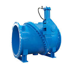
Tilting Disc type three eccentric hard seal check valve, highly efficient energy-saving check valve, is a new and high performance check valve developed by our company combined with many years of valve production technology and advanced foreign products.
It is suitable for water or oil in the pump outlet or water supply and drainage system to prevent water hammer destruction. It is important equipment. to prevent the media backwater and destructive water hammer in the pipeline pump normal or accident to stop. The main advantage is to achieve non-impact operation by overcoming the swing-type and lift check valve‘s impact, water hammer phenomenon.

Features Benefits
1. Valve with large eccentric and multiple eccentric structure, valve plate with butterfly-shaped disc structure, with a small flow resistance characteristics.
2. The use of hydraulic damping device to slow the valve plate to produce, effectively prevent the damage of the sealing pair.
3. Seat design for the tilt, close the trip and time is short, completely avoid water hammer damage to the pump.
4. Valve body cavity flow channel area is greater than the diameter of 40% of the area, the media through the valve plate after almost no pressure drop, head loss. Compared with the general check valve, greatly reducing energy consumption.
5. tilt the seat design, the entire headstock angle of 40 °, tour to 1/2 swing check valves. Opening closing time is short, energy-saving effect.
6. With a unique under the set (also on the set) of the cylinder buffer mechanism, the valve plate closed in place before the slow closing 5 °. Valve plate axis rotation is more flexible, can save a lot of energy.
7. Unattended, no external signal control valve work. Hydraulic damping slow-closing device is an independent system, can be adjusted according to working conditions, without oil or power to control it, no maintenance, environmental protection and energy saving, lower operating costs
8. Swashplate type three eccentric hard seal check valve is suitable for horizontal or vertical installation on the pipeline.
Structure
The three-eccentric hard-seal check valve of the energy-saving type adopts a three eccentric structure, and consists of a valve body, a valve disc, a valve shaft, a valve seat and a damping mechanism.
The valve body consists of two parts. Two parts of the body in the flange, the body of the valve plate, valve seat tilt arrangement, and the body flow channel centerline angle of 55 °. The cavity surface area is greater than the valve body diameter area 40%, the entire valve flow resistance coefficient is small.
Seat and runner center line at a certain angle. Seal surface of the valve seat is part of the oblique cone, and the sealing line formed between the valve seat and the valve disc is an approximate elliptic curve. The angle between the plane of the elliptical sealing line and the centerline of the valve flow channel is 55 degrees ; The approximate ellipse seal line center of the long axis and the cone axis to form an angle of eccentricity, namely the valve seat sealing surface in the cone axis and the valve body flow channel center line formed between the angle (β) 10 ~ 15 ° , The axis of the rotary axis of the valve disc is eccentric with respect to the axis of the cone and forms an eccentricity (E1), and is also eccentric with respect to the plane of the sealing line.
The valve disc is butterfly disc type valve disc, streamline structure design. When the media pressure reaches its working pressure, the valve automatically opens; when the media pressure decreases, the butterfly-shaped valve disc automatically closed.
The valve shaft is a two-stage structure, with self-lubricating bushings, flexible rotation, opening and closing effort.
Unique damping mechanism mainly by the fuel tank, springs, buffer rod, piston and needle valve components. When the valve disc is closed to the last 5 °, the buffer bar to slowly close the valve plate, the valve seat to achieve non-impact, non-collision and no noise to close the seal.
working principle


Technical performance
1. Energy conservation
Energy saving: This tilting disc check valve has the characteristics of energy-saving operation, it is slow closing, wear-resistant, no leakage and the characteristics of a variety of applications can be competent harsh working conditions. Because it has the lowest pressure loss characteristics in any of today's check valve types. Ultra-low head loss is achieved by streamlined valve body design, hydrodynamic design of the valve, the valve cavity is greater than the nominal diameter of 40% of the flow area to achieve. Energy saving is achieved through the application of a 55 ° inclined disc check valve instead of the traditional 90 ° swing check valve to reduce the opening and closing stroke to achieve the purpose of saving energy costs and reduce the use of the valve cost.
Slow Closing: The sloping valve flap is characterized by the use of a short valve stroke, a unique valve reaction, and a fixed shaft pin without a stem packing. First, the traditional swing check valve has 80 ° ~ 90 ° stroke, this tilt valve is only 40 ° stroke, through this tilt angle of the valve seat design to achieve a shorter valve stroke. It is evident that the short stroke reduces the closing time of the valve flap and reduces the return time and the water hammer impact due to the return flow. Second, the valve is the reaction of the eccentric shaft to the valve is divided into about 1/3 or 2/3 position, the shaft through the 1/3 flow reaction under the axis of the 2/3 flow, the anti-use through the buffer itself Reducing the impact of the valve flap, while the traditional swing check valve does not have this feature. Finally, the traditional swing check valve is a rotary valve stem with packing, while the inclined seat check valve without packing, the valve can be free to rotate around the shaft, reducing friction and accelerate the closure of the valve.
2, high-performance
Leak-tight sealing: Leak-tight sealing is achieved by using a 20 ° sealing angle. The 20 ° sealing angle has excellent conical sealing performance and is free of binding and automatic release characteristics. A small amount of valve shaft clearance allows the valve to be sealed against the valve seat without interference from the valve shaft.
Long-life stability: eccentric valve shaft can make the valve in the case of non-sliding and shackled tilt out of the seat, a unique tilt to reduce the valve seat and valve wear, the valve life extension. Hydrodynamic design of the valve flap, both in high flow or low flow medium case, the fluid resistance is very small, can guarantee excellent stability and reduce the vibration of the valve flap wear.
3. Applications
Oblique seat check valve is our company's best products in the check valve, it has an unparalleled variety of applications and reliability, can greatly reduce the cost of using the valve. This valve can be used in any installation layout.
In single-pump systems, swash-plate check valves are commonly used in centrifugal and turbo pumps with flow rates of 4-20 ft / s and pressures up to 400 PSI.
In a multi-pump system, the system is set to reduce jitter and improve the system's ability to better apply the valve. The accurate positioning of the limit stop prevents the valve flap from vibrating, regardless of high flow rate or low flow rate, ensuring extremely low head loss characteristics. When the system shuts down, the multi-pump or parallel pump can produce rapid return flow, the flow rate can be constant. Swash-type triple-eccentric hard-seal check valves are equipped with optional hydraulic snubbers on the upper or bottom to help shut the disc in a multi-pump system even in the event of a power failure.
Implementation of standards
| design standards | API6D API594 |
| Flange connection standard | ASME B16.5、ASME B16.47、ASME B16.1 |
| Structure length standard | API6D、 API594 |
| Testing standard | API6D、API594 |
| Pressure and temperature levels | ASME B16.34 |
Performance specification
| Nominal pressure(Class) | 125 | 150 | 250 |
| Shell strength test(MPa) | 2.4 | 3.0 | 6.0 |
|
Hydraulic seal test(MPa) |
1.76 | 2.2 | 4.4 |
|
Pneumatic sealing test(MPa) |
0.6 | ||
| Body material | Cast iron, ductile iron, carbon steel, stainless steel, alloy steel (different temperature conditions selected different materials) | ||
| Operating temperature | -196~550℃ | ||
| Applicable media | Water, steam, gas, oil and so on | ||
Material of parts
| Serial number | Main parts names | material |
| 1 | pointer | stainless steel |
| 2 | Angle plate | stainless steel |
| 3 | Shaft end sealing gland | Cast iron、stainless steel、Aluminum bronze |
| 4 | O-ring | NBR、EPDM |
| 5 | Shaft sleeve | Copper, steel backing self-lubricating |
| 6 | Left valve shaft | 2Cr13、stainless steel、Aluminum bronze etc. |
| 7 | Pin | 2Cr13、stainless steel、Aluminum bronze etc. |
| 8 | Right valve shaft | 2Cr13、Stainless steel, aluminum bronze and so on |
| 9 | Clasp | Carbon steel, stainless steel |
| 10 | Shaft end cover | Carbon steel |
| 11 | Left valve body | Cast iron、Ductile iron、Carbon steel、stainless steel etc. |
| 12 | cap | Ductile iron、Carbon steel、stainless steel、Aluminum bronze |
| 13 | Stoppers | |
| 14 | flange bolts | Carbon steel、stainless steel |
| 15 | Right valve body | Cast iron、Ductile iron、Carbon steel、stainless steel etc. |
| 16 |
Body Seal |
stainless steel、Copper alloy |
| 17 | Butterfly plate | Cast iron、Ductile iron、Carbon steel、stainless steel etc. |
| 18 | Butterfly plate sealing ring | Multi-level sealing ring(stainless steel+graphite、Asbestos board、PTFE)、Copper alloy |
| 19 | Pressure ring | Carbon steel、stainless steel |
| 20 | Screws | Carbon steel、stainless steel |
| 21 | Buffer rod | stainless steel |
| 22 | Cylinder block | Cast iron、Ductile iron、Carbon steel |
| 23 | bushing | Cast iron、Cast steel |
| 24 | piston | Cast iron |
| 25 | Cylinder | Carbon steel |
| 26 | spring | Manganese steel |
| 27 | Cylinder end cover | Carbon steel |
| 28 | Pipe and pipe joints | Carbon steel |
| 29 | Needle valve | stainless steel |
Product appearance

Connection dimensions H47H(T)-10 / 16 / 25 / 40 / CL125 / CL150 / CL250
|
SIZE in |
DN |
ANSI Class |
L | D | D1 | D2 | B | Z-d | H1 | H | F |
Approximate number (kg) |
| 3" | 80 | 125 | 241 | 190 | 152.5 | 19 | 4-19 | 360 | 125 | 305 | 26 | |
| 150 | 190 | 152.5 | 127 | 19 | 4-19 | 28 | ||||||
| 250 | 210 | 168 |
144.5 |
29 | 8-22 | 45 | ||||||
| 4" | 100 | 125 | 292 | 229 | 190.5 | 24 | 8-19 | 380 | 140 | 330 | 37 | |
| 150 | 229 | 190.5 | 157 | 24 | 8-19 | 40 | ||||||
| 250 | 254 | 200 | 176.5 | 32 | 8-22 | 60 | ||||||
| 6" | 150 | 125 | 381 | 279 | 241.5 | 26 | 8-22 | 406 | 165 | 400 | 79 | |
| 150 | 279 | 241.5 | 216 | 26 | 8-22 | 84 | ||||||
| 250 | 318 | 270 | 246.5 | 36.6 | 12-22 | 101 | ||||||
| 8" | 200 | 125 | 495 | 343 | 298.5 | 29 | 8-22 | 432 | 203 | 480 | 143 | |
| 150 | 343 | 298.5 | 270 | 29 | 8-22 | 151 | ||||||
| 250 | 381 | 330 | 303.5 | 41.3 | 12-25 | 160 | ||||||
| 10" | 250 | 125 | 622 | 406 | 362 | 31 | 12-25 | 457 | 241 | 580 | 206 | |
| 150 | 406 | 362 | 324 | 31 | 12-25 | 224 | ||||||
| 250 | 445 | 387 | 357.5 | 47.6 | 16-29 | 262 | ||||||
| 12" | 300 | 125 | 610 | 483 | 432 | 32 | 12-25 | 508 | 280 | 660 | 297 | |
| 150 | 483 | 432 | 391 | 32 | 12-25 | 320 | ||||||
| 250 | 521 | 451 | 418 | 50.8 | 16-32 | 373 | ||||||
| 14" | 350 | 125 | 762 | 533 | 476 | 35 | 12-29 | 533 | 305 | 740 | 420 | |
| 150 | 533 | 476 | 413 | 35 | 12-29 | 448 | ||||||
| 250 | 584 | 514 | 481.5 | 54 | 20-32 | 518 | ||||||
| 16" | 400 | 125 | 762 | 597 | 540 | 37 | 16-29 | 584 | 356 | 810 | 550 | |
| 150 | 597 | 540 | 470 | 37 | 16-29 | 594 | ||||||
| 250 | 648 | 572 | 535 | 57.2 | 20-35 | 680 | ||||||
| 18" | 450 | 125 | 838 | 635 | 578 | 40 | 16-32 | 610 | 381 | 915 | 663 | |
| 150 | 635 | 578 | 533 | 40 | 16-32 | 708 | ||||||
| 250 | 711 | 629 | 592.5 | 60.4 | 24-35 | 827 | ||||||
| 20" | 500 | 125 | 813 | 699 | 635 | 53 | 20-32 | 635 | 406 | 990 | 803 | |
| 150 | 699 | 635 | 584 | 53 | 20-32 | 868 | ||||||
| 250 | 775 | 686 | 649.5 | 63.5 | 24-35 | 918 | ||||||
| 24" | 600 | 125 | 965 | 813 | 749.5 | 48 | 20-35 | 686 | 483 | 1160 | 1248 | |
| 150 | 813 | 749.5 | 692 | 48 | 20-32 | 1351 | ||||||
| 250 | 914 | 813 | 768.5 | 69.9 | 24-41 | 1567 | ||||||
| 30" | 750 | 125 | 1321 | 984 | 914.5 | 54 | 28-35 | 889 | 584 | 1397 | 2278 | |
| 150 | 984 | 914.5 | 857 | 76 | 28-35 | 2464 | ||||||
| 250 | 1092 | 997 | 945 | 76.2 | 28-51 | 2760 | ||||||
| 36" | 900 | 125 | 1511 | 1168 | 1086 | 60.4 | 32-41 | 990 | 686 | 1650 | 3458 | |
| 150 | 1168 | 1086 | 1022 | 90.4 | 32-41 | 3747 | ||||||
| 250 | 1270 | 1168 | 1110 | 85.7 | 32-57 | 4140 | ||||||
| 42" | 1050 | 125 | 1588 | 1346 | 1257 | 66.7 | 36-41 | 1092 | 813 | 1854 | 4840 | |
| 150 | 1346 | 1257 | 1194 | 96.7 | 36-41 | 5248 | ||||||
| 250 | 1448 | 1340 | 1281 | 93.7 | 36-57 | 5751 | ||||||
| 48" | 1200 | 125 | 1651 | 1511 | 1422 | 70 | 44-41 | 1320 | 940 | 2082 | 6336 | |
| 150 | 1511 | 1422 | 1359 | 108 | 44-41 | 6881 | ||||||
| 250 | 1651 | 1543 | 1484 | 102 | 40-57 | 7683 | ||||||
| 54" | 1350 | 125 | 1981 | 1683 | 1594 | 1511 | 76 | 44-51 | 1397 | 990 | 2260 | 8037 |
| 150 | 1683 | 1594 | 1511 | 120 | 44-51 | 8718 | ||||||
| 250 | 9900 | |||||||||||
| 60" | 1500 | 125 | 2210 | 1854 | 1759 | 79.4 | 52-51 | 1625 | 1067 | 2515 | 10530 | |
| 150 | 1854 | 1759 | 1676 | 132 | 52-51 | 11440 | ||||||
| 250 | 12920 |
Three eccentric hard seal butterfly check valve HBH747H

Usage overview
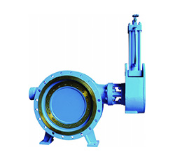
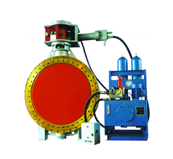
HBH747H Three eccentric hard butterfly check valve is my company set a variety of advanced technology development and the development of a new generation of slow closing check valve. The valve is widely used in metallurgy, hydropower, thermal power, heat, petrochemical, water conservancy, municipal and other industries, the use of independent adjustable hydraulic damping slow closing system for working conditions, pipeline and media parameters of the valve hydraulic damping slow closing The device is adjusted to the best position, installed in the pump outlet and water supply and drainage lines to prevent the media back to prevent water hammer impact, can effectively protect the machine, pump and pipeline safety.
Features Benefits
1. Set-back, cut-off and elimination of water hammer multiple functions in one valve. Reduce the cost of purchase valve, high economy.
2. Automatically closed after the first fast off quickly closed action; fast off without resistance, slow closed anhydrous hammer. To ensure system security, reliability and strong.
3. Hydraulic damping slow closing device is a stand-alone system, can be adjusted according to working conditions, without oil or power to control, no maintenance, environmental protection and energy saving, lower operating costs.
4. Heavy hammer balance mechanism is also adjustable to improve the ability of the valve to adapt to conditions.
5. Slow start the pump, Kai valve after the valve inlet pressure reaches a predetermined value, the valve was open, can reduce the Kai pump current to ensure that the electrical and electronic control system security. Stop the pump when the first fast off after the slow closure, effectively prevent water hammer.
6. The use of butterfly valve structure, with small size, light weight, small footprint, reduce construction costs.
7. Three-dimensional eccentric + large eccentric seal structure, to open the seal that is isolated, close contact with the seal, reducing seal wear and prolong service life.
8. Metal + graphite sandwich seals, progressive seal, tightly sealed, and has anti-sediment and pressure automatic compensation function. Easy to replace and adjust, the sealing effect is good, for a wide range.
9. The nature of the fire design, high security.
10. Set butterfly valve, check valve features in one, plus a unique hydraulic slow closing system, the performance significantly.
working principle

1.Open the valve
Start the pump, the valve before the media pressure increases to the set value, the media acting on the force of the valve plate will slowly open to full-open position, the set value and the size of the hammer arm.
When the valve is opened, the hydraulic oil in the cylinder flows through the check valve from the needle valve, avoiding the pressure of the cylinder, so that the valve can be opened flexibly. Valve slow closing device has a limit device to ensure that the valve plate will not open over.
2.shut down valve
When the media pressure before the valve suddenly decreases, the valve plate in the media back and under the action of heavy hammer closed.
Valve closing process using two stages of buffer: 90 ° ~ 15 ° range, the hydraulic oil through the throttle hole through the needle valve, needle valve to adjust the fixed throttling, slow down the valve closing speed, this time the valve is fast closing process; In the 15 ° ~ 0 °, the hydraulic oil flow through the throttle valve, throttling throttle through the throttle to stepless adjustment, this time the valve is a slow off process, from the surface to slow closing effect.
3.adjust
Switch and slow closing time can be adjusted according to the scene, so that the valve is in the best working condition.
Adjust the hydraulic cylinder needle valve, you can adjust the valve opening and closing speed and time.
Adjust the throttle valve on the hydraulic cylinder, you can adjust the valve phase slow closing speed and time.
Model preparation

Implementation of standards
| Manufacturing standards |
B/T5299-1998、GB/T12238-2008、 JB/T8527-1997 |
API B594 BS5153 |
| Flange connection standard |
GB/T9113.1-2000 GB/T17241.6-1998 |
ASME B16.5 / ASME B16.47 AWWA C207 / ISO7005 |
| Structure length standard | GB/T12221-2005 | API 609 / AWWA C504 ISO5752 |
| Testing standard |
GB/T13927-2008 JB/T9092 |
API598 / AWWA C504 ISO 5208 |
Performance specification
| Nominal pressure |
|
||||||
| Shell strength test | 1.5 times PN | ||||||
| Hydraulic seal test | 1.1 times PN | ||||||
| Pneumatic sealing test | 0.6 times PN | ||||||
| Body material | Grey cast iron Z | Ductile iron Q | Carbon steel C | ||||
| Operating temperature | 0~150℃ | -15~300℃ | -29~425℃ | ||||
| Applicable media | Water, steam, gas, oil and so on | Water, steam, gas, oil and so on | Water, steam, gas, oil and so on | ||||
Installation
The installation of the valve is only applicable to horizontal installation (arrow indicates the medium flow, and pressure check valve seal in the opposite direction)
The valve allows the correct installation of the schematic diagram

The valve does not allow the use of the wrong way to install the diagram (2)

The special installation of the valve, but the direction of the need to change the hammer (custom instructions).
Installation diagram (3)

Product appearance

Connection dimensions HBH747H-10 / 16 / 25 / 40 / 150LB / 300LB / 600LB
| Nominal diameter DN(mm) | Structure length(mm) | Dimensions(mm) | Approximate weight(kg) | |||||
| DN | L1 | L2 | H1 | H2 | H | A | B | |
| 200 | 152 | 230 | 211 | 438 | 781 | 200 | 320 | 140 |
| 250 | 165 | 250 | 240 | 480 | 781 | 200 | 320 | 165 |
| 300 | 178 | 270 | 277 | 511 | 847 | 211 | 324 | 180 |
| 350 | 190 | 290 | 300 | 575 | 875 | 211 | 324 | 190 |
| 400 | 216 | 310 | 330 | 650 | 1100 | 236 | 420 | 219 |
| 450 | 222 | 330 | 350 | 675 | 1135 | 236 | 420 | 276 |
| 500 | 229 | 350 | 370 | 700 | 1172 | 236 | 420 | 368 |
| 600 | 267 | 390 | 475 | 835 | 1340 | 263 | 467 | 532 |
| 700 | 292 | 430 | 510 | 880 | 1403 | 263 | 467 | 956 |
| 800 | 318 | 470 | 570 | 935 | 1490 | 263 | 467 | 1240 |
| 900 | 330 | 510 | 615 | 1005 | 1644 | 295 | 607 | 1530 |
| 1000 | 410 | 550 | 660 | 1070 | 1700 | 295 | 607 | 2104 |
| 1200 | 470 | 530 | 700 | 1180 | 1820 | 295 | 607 | 2890 |
| 1400 | 530 | 710 | 940 | 1380 | 1980 | 330 | 720 | 3356 |
| 1600 | 600 | 790 | 1080 | 1520 | 2140 | 330 | 720 | 4400 |
Swing check valve series
H44H Flanged Swing Check Valve
Performance parameters:
◎design standards: ASME B16.34、BS 1868、API 602、API 6D
◎Nominal diameter: DN50-600mm (2"-24")
◎Nominal pressure: PN16-PN250 (CLASS150-CLASS1500)
◎Connecting flange: ASME B16.5、ASME B16.25、EN 1092
◎Material range: carbon steel, alloy steel, stainless steel
◎Sealing material: Stainless steel, alloy steel, copper
◎temperature range: -40-550℃
◎Applicable medium: water, oil, gas, acid and other corrosive media
main feature
◎Suitable for horizontal installation
◎Closed valve fast and flexible, water hammer pressure, easy to open
◎Valve short stroke, high reliability
◎Fluid flow, fluid resistance is small
◎The overall structure, simple and compact
Product appearance

Connection dimensions H44H-150 2"~24"
| NPS | DN | d | D | D1 | D2 | b | f | L | n-Φd | H | WT(Kg) | ||
| RF/BW | RJ | BF | BW | ||||||||||
| 2 | 50 | 51 | 150 | 120.7 | 92.1 | 19.5 | 2 | 203 | 216 | 4-19 | 133 | 17 | 13 |
| 21/2 | 65 | 64 | 180 | 139.7 | 104.8 | 22.7 | 216 | 229 | 4-19 | 151 | 21 | 17 | |
| 3 | 80 | 76 | 190 | 152.4 | 127 | 24.3 | 241 | 254 | 4-19 | 165 | 29 | 24 | |
| 4 | 100 | 102 | 230 | 190.5 | 157.2 | 24.3 | 292 | 305 | 8-19 | 198 | 42 | 36 | |
| 6 | 150 | 152 | 280 | 241.3 | 215.9 | 25.9 | 356 | 369 | 8-22 | 275 | 74 | 62 | |
| 8 | 200 | 203 | 345 | 298.5 | 269.9 | 29 | 495 | 508 | 8-22 | 340 | 108 | 96 | |
| 10 | 250 | 254 | 405 | 362 | 323.8 | 30.6 | 622 | 635 | 12-25 | 355 | 177 | 158 | |
| 12 | 300 | 305 | 485 | 431.8 | 381 | 32.2 | 698 | 711 | 12-25 | 410 | 282 | 238 | |
| 14 | 350 | 337 | 535 | 476.3 | 412.8 | 35.4 | 787 | 800 | 12-29 | 475 | 372 | 324 | |
| 16 | 400 | 387 | 595 | 539.8 | 469.9 | 37 | 914 | 877 | 16-29 | 552 | 570 | 483 | |
| 18 | 450 | 438 | 635 | 577.9 | 533.4 | 40.1 | 978 | 991 | 16-32 | 600 | 665 | 548 | |
| 20 | 500 | 489 | 700 | 635 | 584.2 | 43.3 | 978 | 991 | 20-32 | 660 | 900 | 782 | |
| 24 | 600 | 591 | 815 | 749.3 | 692.2 | 48.1 | 1295 | 1308 | 20-35 | 740 | 1359 | 1150 | |
Note: The above API6D standard design, flange size in accordance with ASME B16.5 standard. If you have different needs, can be customized according to demand.
Connection dimensions H44H-300 2"~24"
| NPS | DN | d | D | D1 | D2 | b | f | L | n-Φd | H | WT(Kg) | ||
| RF/BW | RJ | BF | BW | ||||||||||
| 2 | 50 | 51 | 165 | 127 | 92.1 | 22.7 | 2 | 267 | 283 | 8-19 | 165 | 21 | 16 |
| 21/2 | 65 | 64 | 190 | 149.2 | 104.8 | 25.9 | 292 | 308 | 8-22 | 187 | 32 | 24 | |
| 3 | 80 | 76 | 210 | 168.3 | 127 | 29 | 318 | 334 | 8-22 | 210 | 43 | 35 | |
| 4 | 100 | 102 | 255 | 200 | 157.2 | 32.2 | 356 | 372 | 8-22 | 235 | 61 | 44 | |
| 6 | 150 | 152 | 320 | 269.9 | 215.9 | 37 | 444 | 460 | 12-22 | 360 | 131 | 105 | |
| 8 | 200 | 203 | 380 | 330.2 | 269.9 | 41.7 | 533 | 549 | 12-25 | 370 | 213 | 167 | |
| 10 | 250 | 254 | 445 | 387.4 | 323.8 | 48.1 | 622 | 638 | 16-29 | 385 | 384 | 272 | |
| 12 | 300 | 305 | 520 | 450.8 | 381 | 51.3 | 711 | 727 | 16-32 | 440 | 449 | 375 | |
| 14 | 350 | 337 | 585 | 514.4 | 412.8 | 54.4 | 838 | 854 | 20-32 | 520 | 680 | 560 | |
| 16 | 400 | 387 | 650 | 571.5 | 469.9 | 57.6 | 864 | 880 | 20-35 | 554 | 840 | 710 | |
| 18 | 450 | 432 | 710 | 628.6 | 533.4 | 60.8 | 978 | 994 | 24-35 | 620 | 1025 | 828 | |
| 20 | 500 | 483 | 775 | 685.8 | 584.2 | 64 | 1016 | 1035 | 24-35 | 680 | 1320 | 1070 | |
| 24 | 600 | 584 | 915 | 812.8 | 692.2 | 70.3 | 1346 | 1368 | 24-41 | 770 | 1960 | 1586 | |
Note: The above API6 standard design, flange size in accordance with ASME B16.5 standard. If you have different needs, can be customized according to demand.
Connection dimensions H44H-600 2"~24"
| NPS | DN | d | D | D1 | D2 | b | f | L | n-Φd | H | WT(Kg) | ||
| RF/BW | RJ | BF | BW | ||||||||||
| 2 | 50 | 51 | 165 | 127 | 92.1 | 32.4 | 7 | 292 | 295 | 8-19 | 155 | 36 | 28 |
| 21/2 | 65 | 64 | 190 | 149.2 | 104.8 | 35.6 | 330 | 333 | 8-22 | 178 | 49 | 40 | |
| 3 | 80 | 76 | 210 | 168.3 | 127 | 38.8 | 356 | 359 | 8-22 | 200 | 68 | 57 | |
| 4 | 100 | 102 | 275 | 215.9 | 157.2 | 45.1 | 432 | 435 | 8-25 | 280 | 111 | 83 | |
| 6 | 150 | 152 | 355 | 292.1 | 215.9 | 54.7 | 559 | 562 | 12-29 | 362 | 230 | 191 | |
| 8 | 200 | 200 | 420 | 349.2 | 269.9 | 62.6 | 660 | 663 | 12-32 | 437 | 416 | 361 | |
| 10 | 250 | 248 | 510 | 431.8 | 323.8 | 70.5 | 787 | 790 | 16-35 | 490 | 673 | 543 | |
| 12 | 300 | 299 | 560 | 489 | 381 | 73.7 | 838 | 841 | 20-35 | 528 | 875 | 770 | |
| 14 | 350 | 327 | 605 | 527 | 412.8 | 76.9 | 889 | 892 | 20-38 | 572 | 944 | 773 | |
| 16 | 400 | 375 | 685 | 603.2 | 469.9 | 83.2 | 991 | 994 | 20-41 | 660 | 1220 | 1015 | |
| 18 | 450 | 419 | 745 | 654 | 533.4 | 89.6 | 1092 | 1095 | 20-44 | 720 | 1620 | 1350 | |
| 20 | 500 | 464 | 815 | 723.9 | 584.2 | 95.9 | 1194 | 1200 | 24-44 | 745 | 2120 | 1750 | |
| 24 | 600 | 559 | 940 | 838.2 | 692.2 | 108.6 | 1397 | 1407 | 24-51 | 960 | 3100 | 2520 | |
Note: The above API6D standard design, flange size in accordance with ASME B16.5 standard. If you have different needs, can be customized according to demand.
Connection dimensions H44H-900 2"~24"
| NPS | NPS | d | D | D1 | D2 | b | f | L | n-Φd | H | WT(Kg) | ||
| RF/BW | RJ | BF | BW | ||||||||||
| 2 | 50 | 48 | 215 | 165.1 | 92.1 | 45.1 | 7 | 368 | 371 | 8-25 | 200 | 69 | 52 |
| 21/2 | 65 | 64 | 245 | 190.5 | 104.8 | 48.3 | 419 | 422 | 8-29 | 220 | 93 | 74 | |
| 3 | 80 | 73 | 240 | 190.5 | 127 | 45.1 | 381 | 384 | 8-25 | 280 | 91 | 70 | |
| 4 | 100 | 98 | 290 | 235 | 157.2 | 51.5 | 457 | 460 | 8-32 | 320 | 145 | 112 | |
| 6 | 150 | 146 | 380 | 317.5 | 215.9 | 62.6 | 610 | 613 | 12-32 | 400 | 259 | 218 | |
| 8 | 200 | 191 | 470 | 393.7 | 269.9 | 70.5 | 737 | 740 | 12-38 | 480 | 565 | 448 | |
| 10 | 250 | 238 | 545 | 469.9 | 323.8 | 76.9 | 838 | 841 | 16-38 | 560 | 900 | 733 | |
| 12 | 300 | 282 | 610 | 533.4 | 381 | 86.4 | 965 | 968 | 20-38 | 630 | 1200 | 975 | |
| 14 | 350 | 311 | 640 | 558.8 | 412.8 | 92.8 | 1029 | 1039 | 20-41 | 680 | 1500 | 1024 | |
| 16 | 400 | 356 | 705 | 616 | 469.9 | 95.9 | 1130 | 1143 | 20-44 | 780 | 2130 | 1760 | |
| 18 | 450 | 400 | 785 | 685.8 | 533.4 | 108.6 | 1219 | 1038 | 20-51 | 880 | / | / | |
| 20 | 500 | 445 | 855 | 749.3 | 584.2 | 115 | 1321 | 1334 | 20-54 | 1050 | / | / | |
| 24 | 600 | 533 | 1040 | 901.7 | 692.2 | 146.7 | 1549 | 1568 | 20-67 | 1200 | / | / | |
Note: The above API6D standard design, flange size in accordance with ASME B16.5 standard. If you have different needs, can be customized according to demand.
Connection dimensions H44H-1500 2"~12"
| NPS | DN | d | D | D1 | D2 | b | f | L | n-Φd | H | WT(Kg) | ||
| RF/BW | RJ | BF | BW | ||||||||||
| 2 | 50 | 48 | 215 | 165.1 | 92.1 | 45.1 | 7 | 368 | 371 | 8-26 | 310 | 69 | 49 |
| 21/2 | 65 | 64 | 245 | 190.5 | 104.8 | 48.3 | 419 | 442 | 8-29 | 310 | 93 | 74 | |
| 3 | 80 | 73 | 265 | 203.5 | 127 | 54.7 | 470 | 473 | 8-32 | 330 | 140 | 111 | |
| 4 | 100 | 98 | 310 | 241.3 | 157.2 | 61 | 546 | 549 | 8-35 | 355 | 232 | 185 | |
| 6 | 150 | 146 | 395 | 317.5 | 215.9 | 89.6 | 705 | 711 | 12-38 | 400 | 490 | 375 | |
| 8 | 200 | 191 | 485 | 393.7 | 269.9 | 99.1 | 832 | 842 | 12-45 | 530 | 990 | 803 | |
| 10 | 250 | 238 | 585 | 482.6 | 323.8 | 115 | 991 | 1001 | 12-51 | 560 | 1490 | 1250 | |
| 12 | 300 | 282 | 675 | 571.5 | 381 | 130.9 | 1130 | 1146 | 16-54 | 650 | 1970 | 1625 | |
Note: The above API6D standard design, flange size in accordance with ASME B16.5 standard. If you have different needs, can be customized according to demand.
Connection dimensions H44H-16 DN50~500
| DN | d | L | D | D1 | D2 | f | b | Z-Φd | H | WT(Kg) | |
| 50 | 48 | 230 | 165 | 125 | 102 | 3 | 18 | 4-φ18 | 135 | 21 | |
| 65 | 64 | 290 | 185 | 145 | 122 | 3 | 18 | 8-φ18 | 142 | 28 | |
| 80 | 73 | 310 | 200 | 160 | 138 | 3 | 20 | 8-φ18 | 168 | 88 | |
| 100 | 98 | 350 | 220 | 180 | 158 | 3 | 20 | 8-φ18 | 180 | 58 | |
| 125 | 127 | 400 | 250 | 210 | 188 | 3 | 22 | 8-φ18 | 210 | 92 | |
| 150 | 146 | 480 | 285 | 240 | 212 | 3 | 22 | 8-φ22 | 233 | 130 | |
| 200 | 191 | 600 | 340 | 295 | 268 | 3 | 24 | 12-φ22 | 304 | 210 | |
| 250 | 238 | 730 | 405 | 355 | 320 | 3 | 26 | 12-φ26 | 348 | 294 | |
| 300 | 282 | 850 | 460 | 410 | 378 | 4 | 28 | 12-φ26 | 390 | 367 | |
| 350 | 311 | 980 | 520 | 470 | 438 | 4 | 30 | 16-φ26 | 430 | 410 | |
| 400 | 356 | 1100 | 580 | 525 | 490 | 4 | 32 | 16-φ30 | 468 | 461 | |
| 450 | 400 | 1200 | 640 | 585 | 550 | 4 | 40 | 20-φ30 | 526 | 570 | |
| 500 | 445 | 1250 | 715 | 650 | 610 | 4 | 44 | 20-φ33 | 525 | 850 | |
Note: The data for the conventional data, flange size in accordance with EN1092-1. If you have different needs, can be customized according to demand.
Connection dimensions H44H-25 DN50~500
| DN | d | L | D | D1 | D2 | f | b | Z-Φd | H | WT(Kg) | |
| 50 | 48 | 230 | 165 | 125 | 102 | 3 | 20 | 4-φ18 | 160 | 22 | |
| 65 | 64 | 290 | 185 | 145 | 122 | 3 | 22 | 8-φ18 | 175 | 29 | |
| 80 | 73 | 310 | 200 | 160 | 138 | 3 | 24 | 8-φ18 | 185 | 38 | |
| 100 | 98 | 350 | 235 | 190 | 162 | 3 | 24 | 8-φ22 | 220 | 61 | |
| 125 | 127 | 400 | 270 | 220 | 188 | 3 | 26 | 8-φ26 | 248 | 96 | |
| 150 | 146 | 480 | 300 | 250 | 218 | 3 | 28 | 8-φ26 | 276 | 132 | |
| 200 | 191 | 600 | 360 | 310 | 278 | 3 | 30 | 8-φ26 | 350 | 213 | |
| 250 | 238 | 730 | 425 | 370 | 335 | 3 | 32 | 8-φ30 | 410 | 297 | |
| 300 | 282 | 850 | 485 | 430 | 395 | 4 | 34 | 12-φ30 | 430 | 372 | |
| 350 | 311 | 980 | 555 | 490 | 450 | 4 | 38 | 12-φ33 | 518 | 415 | |
| 400 | 356 | 1100 | 620 | 550 | 505 | 4 | 40 | 12-φ36 | 560 | 480 | |
| 450 | 400 | 1200 | 670 | 600 | 555 | 4 | 46 | 16-φ36 | 582 | 610 | |
| 500 | 445 | 1250 | 730 | 660 | 615 | 4 | 48 | 16-φ36 | 618 | 920 | |
Note: The data for the conventional data, flange size in accordance with EN1092-1. If you have different needs, can be customized according to demand.
Connection dimensions H44H-40 DN50~400
| DN | d | L | D | D1 | D2 | f | b | Z-Φd | H | WT(Kg) | |
| 50 | 48 | 230 | 165 | 125 | 102 | 3 | 20 | 4-φ18 | 169 | 22 | |
| 65 | 64 | 290 | 185 | 145 | 122 | 3 | 22 | 8-φ18 | 173 | 29 | |
| 80 | 73 | 310 | 200 | 160 | 138 | 3 | 24 | 8-φ18 | 185 | 38 | |
| 100 | 98 | 350 | 235 | 190 | 162 | 3 | 24 | 8-φ22 | 220 | 61 | |
| 125 | 127 | 400 | 270 | 220 | 188 | 3 | 26 | 8-φ26 | 248 | 96 | |
| 150 | 146 | 480 | 300 | 250 | 218 | 3 | 28 | 8-φ26 | 270 | 132 | |
| 200 | 191 | 600 | 375 | 320 | 285 | 3 | 34 | 12-φ30 | 342 | 213 | |
| 250 | 238 | 730 | 450 | 385 | 345 | 3 | 38 | 8-φ33 | 401 | 297 | |
| 300 | 282 | 850 | 515 | 450 | 310 | 4 | 42 | 12-φ33 | 432 | 372 | |
| 350 | 311 | 980 | 580 | 510 | 465 | 4 | 46 | 12-φ36 | 455 | 425 | |
| 400 | 356 | 1100 | 660 | 585 | 535 | 4 | 50 | 12-φ39 | 510 | 480 | |
Note: The data for the conventional data, flange size in accordance with EN1092-1. If you have different needs, can be customized according to demand.
Connection dimensions H44H-64 DN50~400
| DN | d | L | D | D1 | D2 | f | b | Z-Φd | H | WT(Kg) | |
| 50 | 48 | 300 | 180 | 135 | 102 | 3 | 26 | 4-φ22 | 177 | 27 | |
| 65 | 64 | 340 | 205 | 160 | 122 | 3 | 26 | 8-φ22 | 197 | 37 | |
| 80 | 73 | 380 | 215 | 170 | 138 | 3 | 28 | 8-φ22 | 212 | 57 | |
| 100 | 98 | 430 | 250 | 200 | 162 | 3 | 30 | 8-φ26 | 248 | 89 | |
| 125 | 127 | 500 | 295 | 240 | 188 | 3 | 34 | 8-φ30 | 296 | 135 | |
| 150 | 146 | 550 | 345 | 280 | 218 | 3 | 36 | 8-φ33 | 330 | 184 | |
| 200 | 191 | 650 | 415 | 345 | 285 | 3 | 42 | 12-φ36 | 385 | 266 | |
| 250 | 238 | 775 | 470 | 400 | 345 | 3 | 46 | 8-φ36 | 445 | 396 | |
| 300 | 282 | 900 | 530 | 460 | 410 | 4 | 52 | 12-φ36 | 474 | 643 | |
| 350 | 311 | 1025 | 600 | 525 | 465 | 4 | 56 | 12-φ39 | 514 | 815 | |
| 400 | 356 | 1150 | 670 | 585 | 535 | 4 | 60 | 12-φ42 | 616 | 1234 | |
Note: The data for the conventional data, flange size in accordance with EN1092-1. If you have different needs, can be customized according to demand.
Lift check valve Series
H71H Wafer type Lift check valve
Performance parameters:
◎design standards: API 594、BS 1868、API 6D
◎Nominal diameter: DN15-200mm (1/2"-8")
◎Nominal pressure: PN10-PN160 (CLASS 150-CLASS 900)
◎Connecting flange: ASME B16.5
◎Material range: carbon steel, alloy steel, stainless steel
◎Sealing material: stainless steel, alloy steel, copper
◎temperature range: -100-550℃
◎Applicable medium: water, oil, gas, acid and other corrosive media
main feature
◎Valve short stroke, close the impact of small, high reliability
◎Open the pressure is small, a small pressure to open the valve flap
◎Wafer-type horizontal or vertical installation can be, only horizontal flange-type installation
◎Closed valve fast and flexible, water hammer pressure, easy to open
◎The overall structure, simple and compact
Product appearance

Connection dimensions H71H-150 1/2"~8"
|
NPS |
L | Flange dimensions | Pipe flange noun engin |
WT (Kg) |
||||||
| D | D2 | D3 | D4 | L1 | D1 | n-Md | ||||
| RF | RJ | |||||||||
| 1/2 | 25 | 46 | 15 | 25 | 25 | 90 | / | 60.5 | 4-14 | 0.28 |
| 3/4 | 31.5 | 56 | 19 | 30 | 30 | 100 | / | 70 | 4-14 | 0.42 |
| 1 | 35.5 | 65 | 24 | 36 | 36 | 105 | 120 | 79.5 | 4-14 | 0.56 |
| 1 1/4 | 40 | 74 | 31 | 43 | 43 | 115 | 130 | 89 | 4-14 | 0.75 |
| 1 1/2 | 45 | 84 | 39 | 52 | 52 | 120 | 135 | 98.5 | 4-14 | 1.3 |
| 2 | 56 | 103 | 48 | 62 | 62 | 140 | 155 | 120.5 | 4-16 | 2.1 |
| 2 1/2 | 63 | 122 | 62 | 75 | 75 | 155 | 170 | 139.5 | 4-16 | 2.8 |
| 3 | 71 | 135 | 76 | 90 | 90 | 165 | 180 | 152.5 | 4-16 | 3.6 |
| 4 | 80 | 173 | 95 | 112 | 112 | 175 | 190 | 190.5 | 8-16 | 4.8 |
| 5 | 110 | 195 | 110 | 125 | 132 | 210 | 225 | 216 | 8-20 | 12 |
| 6 | 125 | 220 | 127 | 150 | 158 | 230 | 245 | 241.5 | 8-20 | 17 |
| 8 | 160 | 277 | 165 | 200 | 208 | 270 | 285 | 298.5 | 8-20 | 29 |
Note: The above API standard design, flange size in accordance with ASME standards. If you have different needs, can be customized according to demand.
Connection dimensions H71H-300 1/2"~6"
|
NPS |
L | Flange dimensions | Pipe flange noun engin |
WT (Kg) |
||||||
| D | D2 | D3 | D4 | L1 | D1 | n-Md | ||||
| RF | RJ | |||||||||
| 1/2 | 25 | 52 | 15 | 25 | 25 | 95 | 105 | 66.5 | 4-14 | 0.3 |
| 3/4 | 31.5 | 65 | 19 | 30 | 30 | 110 | 125 | 82.5 | 4-16 | 0.46 |
| 1 | 35.5 | 72 | 24 | 36 | 36 | 115 | 130 | 89 | 4-16 | 0.6 |
| 1 1/4 | 40 | 81 | 31 | 43 | 43 | 125 | 140 | 98.5 | 4-16 | 0.8 |
| 1 1/2 | 45 | 94 | 39 | 52 | 52 | 140 | 155 | 114.5 | 4-20 | 1.5 |
| 2 | 56 | 110 | 48 | 62 | 62 | 145 | 170 | 127 | 8-16 | 2.4 |
| 2 1/2 | 63 | 128 | 62 | 75 | 75 | 170 | 190 | 149 | 8-20 | 3 |
| 3 | 71 | 147 | 76 | 90 | 90 | 185 | 205 | 168 | 8-20 | 4 |
| 4 | 80 | 179 | 95 | 112 | 112 | 200 | 220 | 200 | 8-20 | 5.5 |
| 5 | 110 | 214 | 110 | 125 | 132 | 235 | 255 | 235 | 8-20 | 13 |
| 6 | 125 | 249 | 127 | 150 | 158 | 255 | 275 | 270 | 12-20 | 22 |
| 8 | 160 | 305 | 165 | 200 | 208 | 305 | 325 | 330 | 12-24 | 36 |
Note: The above API standard design, flange size in accordance with ASME standards. If you have different needs, can be customized according to demand.
Connection dimensions H71H-600 1/2"~8"
| NPS | L | Flange dimensions | Pipe flange noun engin |
WT (Kg) |
||||||
| D | D2 | D3 | D4 | L1 | D1 | n-Md | ||||
| RF | RJ | |||||||||
| 1/2 | 25 | 52 | 15 | 25 | 25 | 95 | 105 | 66.5 | 4-14 | 0.4 |
| 3/4 | 31.5 | 65 | 19 | 30 | 30 | 110 | 125 | 82.5 | 4-16 | 0.8 |
| 1 | 35.5 | 72 | 24 | 36 | 36 | 115 | 130 | 89 | 4-16 | 1 |
| 1 1/4 | 40 | 81 | 31 | 43 | 43 | 125 | 140 | 98.5 | 4-16 | 1.3 |
| 1 1/2 | 45 | 94 | 39 | 52 | 52 | 145 | 160 | 114.5 | 4-20 | 1.8 |
| 2 | 56 | 110 | 48 | 62 | 62 | 155 | 170 | 127 | 8-16 | 2.8 |
| 2 1/2 | 63 | 128 | 62 | 75 | 75 | 175 | 195 | 149 | 8-20 | 4 |
| 3 | 71 | 147 | 76 | 90 | 90 | 190 | 210 | 168.5 | 8-20 | 6 |
| 4 | 80 | 191 | 95 | 112 | 112 | 220 | 240 | 216 | 8-24 | 11 |
| 5 | 110 | 239 | 110 | 125 | 132 | 265 | 285 | 267 | 8-27 | 25 |
| 6 | 125 | 264 | 127 | 150 | 158 | 290 | 310 | 292 | 12-27 | 32 |
| 8 | 160 | 318 | 165 | 200 | 208 | 345 | 365 | 349 | 12-30 | 52 |
Note: The above API standard design, flange size in accordance with ASME standards. If you have different needs, can be customized according to demand.
Connection dimensions H71H-900 1/2"~6"
|
NPS |
L | Flange dimensions | Pipe flange noun engin |
WT (Kg) |
||||||
| D | D2 | D3 | D4 | L1 | D1 | n-Md | ||||
| RF | RJ | |||||||||
| 1/2 | 25 | 62 | 15 | 25 | 25 | 125 | 140 | 82.5 | 4-20 | 0.6 |
| 3/4 | 31.5 | 69 | 19 | 30 | 30 | 135 | 150 | 89 | 4-20 | 0.9 |
| 1 | 35.5 | 77 | 24 | 36 | 36 | 155 | 170 | 101.5 | 4-24 | 1.2 |
| 1 1/4 | 40 | 87 | 31 | 43 | 43 | 160 | 175 | 111 | 4-24 | 1.5 |
| 1 1/2 | 45 | 97 | 39 | 52 | 52 | 175 | 190 | 124 | 4-27 | 2 |
| 2 | 56 | 140 | 48 | 62 | 62 | 195 | 210 | 165 | 8-24 | 5.5 |
| 2 1/2 | 63 | 162 | 62 | 75 | 75 | 215 | 230 | 190.5 | 8-27 | 7.5 |
| 3 | 71 | 165 | 76 | 90 | 90 | 210 | 225 | 190.5 | 8-24 | 8 |
| 4 | 80 | 204 | 95 | 112 | 112 | 245 | 265 | 235 | 8-30 | 14 |
| 5 | 110 | 245 | 110 | 125 | 132 | 290 | 310 | 279.5 | 8-33 | 27 |
| 6 | 125 | 286 | 127 | 150 | 158 | 310 | 325 | 317.5 | 12-30 | 41 |
| 8 | 160 | 356 | 165 | 200 | 208 | 375 | 390 | 393.5 | 12-36 | 76 |
Note: The above API standard design, flange size in accordance with ASME standards. If you have different needs, can be customized according to demand.

Main profile and main connection dimensions PN16.0MPa~32.0MPa
| Nominal pressure | Main dimensions and connection dimensions |
weight (kg) |
|||||||
| DN | D | M | D2 | D0 | L0 | D | L | ||
| 16.0MPa | 15 | 95 | M24×2 | 20 | 16 | 145 | 42 | 60 | 5 |
| 25 | 105 | M33×2 | 28 | 23 | 155 | 50 | 65 | 10 | |
| 32 | 115 | M42×2 | 37 | 29 | 175 | 65 | 80 | 15 | |
| 40 | 165 | M52×2 | 42 | 39 | 215 | 72 | 90 | 20 | |
| 50 | 165 | M64×2 | 58 | 50 | 245 | 88 | 115 | 30 | |
| 65 | 200 | M80×2 | 73 | 65 | 300 | 115 | 140 | 45 | |
| 80 | 225 | M100×2 | 93 | 80 | 345 | 135 | 160 | 60 | |
| 32.0MPa | 15 | 105 | M33×2 | 27 | 17 | 155 | 50 | 65 | 5 |
| 25 | 115 | M42×2 | 35 | 22 | 175 | 62 | 80 | 10 | |
| 32 | 135 | M48×2 | 41 | 30 | 200 | 72 | 90 | 15 | |
| 40 | 165 | M60×2 | 58 | 42 | 245 | 88 | 115 | 20 | |
| 50 | 200 | M80×2 | 70 | 58 | 300 | 115 | 140 | 30 | |
| 65 | 215 | M100×2 | 90 | 68 | 345 | 135 | 160 | 45 | |
| 80 | 260 | M125×2 | 112 | 85 | 395 | 165 | 185 | 60 | |
Double disc check valve Series
H76H Wafer Double disc check valve
Performance parameters:
◎Design standard: API 594、API 6D、GB/T 8937
◎Nominal diameter: DN50-1200mm (2"-48")
◎Nominal pressure: PN10-PN420 (CLASS150-2500)
◎Pipe Flange: API 605、ASME B16.5、ASME B16.47、GB/T 9112、GB/T 1724.1
◎Material range: Carbon steel, alloy steel, stainless steel, copper alloy
◎Sealing material: Stainless steel, alloy steel, copper, rubber oil, gas, acid and other corrosive media
◎temperature range: -100-730℃
◎Applicable medium: Water, oil, gas, acid and other corrosive media
main feature
◎Structure length is short
◎Small size and light weight
◎Horizontal or vertical pipe can be, easy to install and flexible
◎Closed valve fast and flexible, water hammer pressure, easy to open
◎Valve short stroke, close the impact of small, high reliability
◎Fluid flow, fluid resistance is small
◎The overall structure, simple and compact
Product appearance

Connection dimensions H76H-150 2"~48"
|
NPS |
L | Flange dimensions | Pipe flange noun engin |
WT Kg |
|||||
| D | D2 | D3 | L1 | D1 | n-Md | ||||
| RF | RJ | ||||||||
| 2 | 60 | 103 | 51 | 56 | 140 | 155 | 120.5 | 4-16 | 2 |
| 2 1/2 | 67 | 122 | 65 | 73 | 150 | 165 | 139.5 | 4-16 | 3 |
| 3 | 73 | 135 | 80 | 88 | 160 | 175 | 152.5 | 4-16 | 4 |
| 4 | 73 | 173 | 102 | 108 | 170 | 185 | 190.5 | 8-16 | 6 |
| 5 | 86 | 195 | 127 | 132 | 190 | 205 | 216 | 8-20 | 8 |
| 6 | 98 | 220 | 152 | 160 | 205 | 220 | 241 | 8-20 | 13 |
| 8 | 127 | 277 | 203 | 210 | 240 | 255 | 298 | 8-20 | 25 |
| 10 | 146 | 337 | 254 | 266 | 270 | 285 | 362 | 12-24 | 39 |
| 12 | 181 | 407 | 305 | 310 | 310 | 325 | 432 | 12-24 | 64 |
| 14 | 184 | 448 | 350 | 355 | 325 | 340 | 476 | 12-27 | 85 |
| 16 | 191 | 512 | 400 | 405 | 340 | 355 | 540 | 12-27 | 114 |
| 18 | 203 | 547 | 450 | 455 | 365 | 380 | 578 | 16-27 | 138 |
| 20 | 219 | 604 | 500 | 505 | 385 | 400 | 635 | 20-30 | 163 |
| 24 | 222 | 715 | 600 | 605 | 405 | 420 | 749 | 20-33 | 285 |
| 28 | 305 | 773 | 700 | 700 | 455 | / | 795 | 40-20 | 380 |
| 30 | 305 | 824 | 746 | 750 | 455 | / | 846 | 44-20 | 425 |
| 32 | 305 | 878 | 796 | 800 | 460 | / | 900 | 48-20 | 560 |
| 36 | 368 | 983 | 898 | 910 | 540 | / | 1009.5 | 44-24 | 640 |
| 42 | 432 | 1142 | 1050 | 1055 | 625 | / | 1171.5 | 48-27 | / |
| 48 | 542 | 1302 | 1200 | 1205 | 740 | / | 1335 | 44-30 | / |
Note: The above API standard design, flange size in accordance with ASME standards. If you have different needs, can be customized according to demand.
Connection dimensions H76H-300 2"~48"
|
NPS |
L | Flange dimensions | Pipe flange noun engin |
WT Kg |
|||||
| D | D2 | D3 | L1 | D1 | n-Md | ||||
| RF | RJ | ||||||||
| 2 | 60 | 110 | 51 | 58 | 155 | 175 | 127 | 8-16 | 3 |
| 2 1/2 | 67 | 128 | 65 | 73 | 175 | 195 | 149 | 8-20 | 4 |
| 3 | 73 | 147 | 80 | 88 | 190 | 210 | 168.5 | 8-20 | 6 |
| 4 | 73 | 179 | 102 | 108 | 195 | 215 | 200 | 8-20 | 8 |
| 5 | 86 | 214 | 127 | 132 | 215 | 235 | 235 | 8-20 | 15 |
| 6 | 98 | 249 | 152 | 160 | 230 | 250 | 270 | 12-20 | 18 |
| 8 | 127 | 305 | 203 | 210 | 280 | 300 | 330 | 12-24 | 31 |
| 10 | 146 | 359 | 254 | 266 | 315 | 335 | 387.5 | 16-27 | 51 |
| 12 | 181 | 420 | 305 | 310 | 365 | 385 | 451 | 16-30 | 83 |
| 14 | 222 | 483 | 350 | 355 | 410 | 430 | 514.5 | 20-30 | 117 |
| 16 | 232 | 537 | 400 | 405 | 435 | 455 | 517.5 | 20-33 | 190 |
| 18 | 264 | 594 | 450 | 455 | 475 | 495 | 628.5 | 24-33 | 200 |
| 20 | 292 | 652 | 500 | 505 | 510 | 535 | 686 | 24-33 | 265 |
| 24 | 318 | 772 | 600 | 608 | 560 | 585 | 813 | 24-39 | 410 |
| 30 | 368 | 882 | 735 | 740 | 650 | 675 | 921 | 36-36 | 660 |
| 36 | 483 | 1044 | 873 | 880 | 800 | 828 | 1089 | 32-42 | 1020 |
| 42 | 568 | 1196 | 1035 | 1045 | 920 | / | 1245 | 36-45 | 1540 |
| 48 | 629 | 1365 | 1179 | 1190 | 1010 | / | 1416 | 40-48 | 2260 |
Note: The above API standard design, flange size in accordance with ASME standards. If you have different needs, can be customized according to demand.
Connection dimensions H76H-600 2"~24"
|
NPS |
L | Flange dimensions | Pipe flange noun engin |
WT Kg |
|||||
| D | D2 | D3 | L1 | D1 | n-Md | ||||
| RF | RJ | ||||||||
| 2 | 60 | 110 | 51 | 58 | 175 | 180 | 127 | 8-16 | 4 |
| 2 1/2 | 67 | 128 | 65 | 73 | 195 | 200 | 149 | 8-20 | 5 |
| 3 | 73 | 147 | 80 | 88 | 210 | 215 | 168.5 | 8-20 | 8 |
| 4 | 79 | 191 | 102 | 108 | 235 | 240 | 216 | 8-24 | 11 |
| 5 | 105 | 239 | 127 | 136 | 280 | 285 | 267 | 8-27 | 20 |
| 6 | 136 | 264 | 152 | 162 | 320 | 325 | 292 | 12-27 | 26 |
| 8 | 165 | 318 | 200 | 212 | 370 | 375 | 349 | 12-30 | 55 |
| 10 | 213 | 398 | 250 | 266 | 440 | 445 | 432 | 16-33 | 103 |
| 12 | 229 | 455 | 305 | 312 | 460 | 465 | 489 | 20-33 | 140 |
| 14 | 273 | 490 | 337 | 355 | 520 | 525 | 527 | 20-36 | 223 |
| 16 | 305 | 562 | 387 | 400 | 575 | 580 | 603 | 20-39 | 360 |
| 18 | 362 | 610 | 438 | 450 | 650 | 655 | 654 | 20-42 | 395 |
| 20 | 368 | 680 | 487 | 500 | 670 | 680 | 724 | 24-42 | 518 |
| 24 | 438 | 786 | 591 | 600 | 780 | 790 | 838 | 24-48 | 836 |
Note: The above API standard design, flange size in accordance with ASME standards. If you have different needs, can be customized according to demand.
Connection dimensions H76H-900 2"~14"
|
NPS |
L | Flange dimensions | Pipe flange noun engin |
WT Kg |
|||||
| D | D2 | D3 | L1 | D1 | n-Md | ||||
| RF | RJ | ||||||||
| 2 | 70 | 140 | 51 | 58 | 225 | 230 | 165 | 8-24 | 8 |
| 2 1/2 | 83 | 162 | 65 | 73 | 250 | 255 | 190 | 8-27 | 11 |
| 3 | 83 | 165 | 80 | 90 | 240 | 245 | 190 | 8-24 | 14 |
| 4 | 102 | 204 | 102 | 108 | 285 | 290 | 235 | 8-30 | 20 |
| 5 | 110 | 245 | 127 | 136 | 310 | 315 | 279.5 | 8-33 | 30 |
| 6 | 159 | 286 | 150 | 162 | 365 | 370 | 317.5 | 12-30 | 45 |
| 8 | 206 | 356 | 200 | 212 | 440 | 445 | 393.5 | 12-36 | 84 |
| 10 | 241 | 432 | 250 | 266 | 490 | 495 | 470 | 16-36 | 145 |
| 12 | 292 | 495 | 305 | 312 | 560 | 565 | 535.5 | 20-36 | 220 |
| 14 | 356 | 518 | 377 | 355 | 645 | 655 | 559 | 20-39 | 350 |
| 16 | 384 | 572 | 387 | 400 | 685 | 695 | 616 | 20-42 | 470 |
| 18 | 451 | 635 | 438 | 450 | 790 | 805 | 686 | 20-48 | 605 |
| 20 | 451 | 695 | 487 | 496 | 810 | 825 | 749.5 | 20-52 | 820 |
| 24 | 495 | 835 | 591 | 600 | 945 | 965 | 901.5 | 20-64 | 1050 |
Note: The above API standard design, flange size in accordance with ASME standards. If you have different needs, can be customized according to demand.
Connection dimensions H76H-1500 2"~16"
|
NPS |
L | Flange dimensions | Pipe flange noun engin |
WT Kg |
|||||
| D | D2 | D3 | L1 | D1 | n-Md | ||||
| RF | RJ | ||||||||
| 2 | 70 | 110 | 51 | 58 | 175 | 180 | 127 | 8-16 | 4 |
| 2 1/2 | 83 | 128 | 65 | 73 | 195 | 200 | 149 | 8-20 | 5 |
| 3 | 83 | 147 | 80 | 88 | 210 | 215 | 168.5 | 8-20 | 8 |
| 4 | 102 | 191 | 102 | 108 | 235 | 240 | 216 | 8-24 | 11 |
| 5 | 110 | 239 | 127 | 136 | 280 | 285 | 267 | 8-27 | 20 |
| 6 | 159 | 264 | 152 | 162 | 320 | 325 | 292 | 12-27 | 26 |
| 8 | 206 | 318 | 200 | 212 | 370 | 375 | 349 | 12-30 | 55 |
| 10 | 248 | 398 | 250 | 266 | 440 | 445 | 432 | 16-33 | 103 |
| 12 | 305 | 455 | 305 | 312 | 460 | 465 | 489 | 20-33 | 140 |
| 14 | 356 | 490 | 377 | 355 | 520 | 525 | 527 | 20-36 | 223 |
| 16 | 384 | 562 | 387 | 400 | 575 | 580 | 603 | 20-39 | 360 |
Note: The above API standard design, flange size in accordance with ASME standards. If you have different needs, can be customized according to demand.
Connection dimensions H76H-2500 2"~12"
|
NPS |
L | Flange dimensions | Pipe flange noun engin |
WT Kg |
|||||
| D | D2 | D3 | L1 | D1 | n-Md | ||||
| RF | RJ | ||||||||
| 2 | 70 | 140 | 51 | 58 | 225 | 230 | 165 | 8-24 | 8 |
| 2 1/2 | 83 | 162 | 65 | 73 | 250 | 255 | 190 | 8-27 | 11 |
| 3 | 83 | 165 | 80 | 90 | 240 | 245 | 190 | 8-24 | 14 |
| 4 | 105 | 204 | 102 | 108 | 285 | 290 | 235 | 8-30 | 20 |
| 5 | 110 | 245 | 127 | 136 | 310 | 315 | 279.5 | 8-33 | 30 |
| 6 | 159 | 286 | 150 | 162 | 365 | 370 | 317.5 | 12-30 | 45 |
| 8 | 206 | 356 | 200 | 212 | 440 | 445 | 393.5 | 12-36 | 84 |
| 10 | 254 | 432 | 250 | 266 | 490 | 495 | 470 | 16-36 | 145 |
| 12 | 305 | 495 | 305 | 312 | 560 | 565 | 533.5 | 20-36 | 220 |
Note: The above API standard design, flange size in accordance with ASME standards. If you have different needs, can be customized according to demand.
H74H Wafer type single lobe check valve
Performance parameters:
◎design standards: API 594、API 6D、GB/T 8937
◎Nominal diameter: DN50-600mm (2"-24")
◎Nominal pressure: PN10-PN150 (CLASS150- CLASS 900)
◎Pipe Flange:API 605、ASME B16.5、ASME B16.47、GB/T 9112、GB/T 1724.1
◎Material range: carbon steel, alloy steel, stainless steel, copper alloy
◎Sealing material: stainless steel, alloy steel, copper, rubber
◎temperature range:-100-730℃
◎Applicable medium: water, oil, gas, acid and other corrosive media
main feature
◎Structure length is short
◎Small size and light weight
◎Horizontal or vertical pipe can be, easy to install and flexible
◎Closed valve fast and flexible, water hammer pressure, easy to open
◎Valve short stroke, close the impact of small, high reliability
◎Fluid flow, fluid resistance is small
◎The overall structure, simple and compact
Product appearance

Connection dimensions H74H-150 2"~24"
| NPS | L | Dimensions | Pipe flange noun engin |
WT Kg |
|||
| D | L 1 (RF) | L 1 (RJ) | D1 | n-Md | |||
| 2 | 60 | 103 | 140 | 155 | 120.5 | 4-16 | 3 |
| 2 1/2 | 67 | 122 | 150 | 165 | 139.5 | 4-16 | 4 |
| 3 | 73 | 135 | 160 | 175 | 152.5 | 4-16 | 5 |
| 4 | 73 | 173 | 170 | 185 | 190.5 | 8-16 | 8 |
| 5 | 86 | 195 | 190 | 205 | 216 | 8-20 | 10 |
| 6 | 98 | 220 | 205 | 220 | 241 | 8-20 | 16 |
| 8 | 127 | 277 | 240 | 255 | 298 | 8-20 | 30 |
| 10 | 146 | 337 | 270 | 285 | 362 | 12-24 | 47 |
| 12 | 181 | 407 | 310 | 325 | 432 | 12-24 | 65 |
| 14 | 184 | 448 | 325 | 340 | 476 | 12-27 | 102 |
| 16 | 191 | 512 | 340 | 355 | 540 | 12-27 | 137 |
| 18 | 203 | 547 | 365 | 380 | 578 | 16-27 | 166 |
| 20 | 219 | 604 | 385 | 400 | 635 | 20-30 | 193 |
| 24 | 222 | 715 | 405 | 420 | 749 | 20-33 | 397 |
Note: The above API standard design, flange size in accordance with ASME standards. If you have different needs, can be customized according to demand.
Connection dimensions H74H-300 2"~24"
| NPS | L | Dimensions | Pipe flange noun engin |
WT Kg |
|||
| D | L 1 (RF) | L 1 (RJ) | D1 | n-Md | |||
| 2 | 60 | 110 | 155 | 175 | 127 | 8-16 | 4 |
| 2 1/2 | 67 | 128 | 175 | 195 | 149 | 8-20 | 5 |
| 3 | 73 | 147 | 190 | 210 | 168.5 | 8-20 | 7 |
| 4 | 73 | 179 | 195 | 215 | 200 | 8-20 | 10 |
| 5 | 86 | 214 | 215 | 235 | 235 | 8-20 | 18 |
| 6 | 98 | 249 | 230 | 250 | 270 | 12-20 | 22 |
| 8 | 127 | 305 | 280 | 300 | 330 | 12-24 | 37 |
| 10 | 146 | 359 | 315 | 335 | 387.5 | 16-27 | 61 |
| 12 | 181 | 420 | 365 | 385 | 451 | 16-30 | 92 |
| 14 | 222 | 483 | 410 | 430 | 514.5 | 20-30 | 140 |
| 16 | 232 | 537 | 435 | 455 | 517.5 | 20-33 | 228 |
| 18 | 264 | 594 | 475 | 495 | 628.5 | 24-33 | 240 |
| 20 | 292 | 652 | 510 | 535 | 686 | 24-33 | 318 |
| 24 | 318 | 772 | 560 | 585 | 813 | 24-39 | 492 |
Note: The above API standard design, flange size in accordance with ASME standards. If you have different needs, can be customized according to demand.
Connection dimensions H74H-600 2"~24"
| NPS | L | Dimensions | Pipe flange noun engin |
WT Kg |
|||
| D | L 1 (RF) | L 1 (RJ) | D1 | n-Md | |||
| 2 | 60 | 110 | 175 | 180 | 127 | 8-16 | 5 |
| 2 1/2 | 67 | 128 | 195 | 200 | 149 | 8-20 | 6 |
| 3 | 73 | 147 | 210 | 215 | 168.5 | 8-20 | 10 |
| 4 | 79 | 191 | 235 | 240 | 216 | 8-24 | 13 |
| 5 | 105 | 239 | 280 | 285 | 267 | 8-27 | 24 |
| 6 | 136 | 264 | 320 | 325 | 292 | 12-27 | 31 |
| 8 | 165 | 318 | 370 | 375 | 349 | 12-30 | 66 |
| 10 | 213 | 398 | 440 | 445 | 432 | 16-33 | 114 |
| 12 | 229 | 455 | 460 | 465 | 489 | 20-33 | 168 |
| 14 | 273 | 490 | 520 | 525 | 527 | 20-36 | 268 |
| 16 | 305 | 562 | 575 | 580 | 603 | 20-39 | 432 |
| 18 | 362 | 610 | 650 | 655 | 654 | 20-42 | 474 |
| 20 | 368 | 680 | 670 | 680 | 724 | 24-42 | 622 |
| 24 | 438 | 786 | 780 | 790 | 838 | 24-48 | 1003 |
Note: The above API standard design, flange size in accordance with ASME standards. If you have different needs, can be customized according to demand.
Connection dimensions H74H-900 2"~24"
|
NPS |
L | Dimensions | Pipe flange noun engin |
WT Kg |
|||
| D | L 1 (RF) | L 1 (RJ) | D1 | n-Md | |||
| 2 | 70 | 140 | 225 | 230 | 165 | 8-24 | 10 |
| 2 1/2 | 83 | 162 | 250 | 255 | 190 | 8-27 | 13 |
| 3 | 83 | 165 | 240 | 245 | 190 | 8-24 | 17 |
| 4 | 102 | 204 | 285 | 290 | 235 | 8-30 | 24 |
| 5 | 110 | 245 | 310 | 315 | 279.5 | 8-33 | 36 |
| 6 | 159 | 286 | 365 | 370 | 317.5 | 12-30 | 50 |
| 8 | 206 | 356 | 440 | 445 | 393.5 | 12-36 | 101 |
| 10 | 241 | 432 | 490 | 495 | 470 | 16-36 | 174 |
| 12 | 292 | 495 | 560 | 565 | 535.5 | 20-36 | 264 |
| 14 | 356 | 518 | 645 | 655 | 559 | 20-39 | 420 |
| 16 | 384 | 572 | 685 | 695 | 616 | 20-42 | 564 |
| 18 | 451 | 635 | 790 | 805 | 686 | 20-48 | 726 |
| 20 | 451 | 695 | 810 | 825 | 749.5 | 20-52 | 984 |
| 24 | 495 | 835 | 945 | 965 | 901.5 | 20-64 | 1260 |
Note: The above API standard design, flange size in accordance with ASME standards. If you have different needs, can be customized according to demand.