Products
- Products
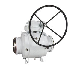
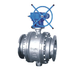
- Trunnion Ball Valves
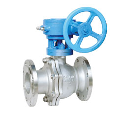
- Floating ball valve
- Metal hard seal ball valve
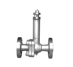
- Cryogenic ball valve
- Fully welded ball valve
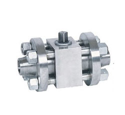
- Threaded, socket weld, butt weld ball valve
Contact us
Tel:+86-577-8682 5111
Email:zjbeize@163.com

Performance parameters
◎design standards:API 6D、ISO14313、BS 5351、GB/T 19672
◎Nominal diameter: DN50-1000mm (2"-40")
◎Nominal pressure: PN16-PN420 (CL150- CL2500)
◎Flange standard: ASME B16.5、ASME B16.47、MSS SP-44、EN1092、ISO7005、JB/T 79.1
◎Butt welding standard: ASME B16.25
◎Material range: carbon steel, alloy steel, stainless steel, duplex steel, titanium alloy
◎Sealing material: PTFE、RPTFE、PEEK、NYLON、MOLON、DELON
◎Operation: handle, worm, electric, pneumatic, gas-liquid linkage, electro-hydraulic linkage
◎temperature range: -46-200℃
◎Applicable medium: water, oil, gas, acid and other corrosive media
Main feature
◎Fireproof design
◎Anti-static design
◎Design of stem anti - blowout
◎Preloaded spring, to ensure a reliable floating valve seat sealing function
◎The secondary sealing structure of the emergency grease sealant device to prevent seat leakage
◎Valve chamber pressure, pressure relief valve automatic discharge
◎Discharge valve discharge in the cavity cavity debris in the accumulation of objects, venting cavity
◎Stem can be extended, buried in the ground can be accessed by a long device
Connection dimensions Q347F-150 4"~36"
| NPS | DN | L | D | D1 | D2 | b | f | Z-Φd | H | H1 |
WT Kg |
|
| RF | BW | |||||||||||
| 4 | 102 | 229 | 305 | 230 | 190.5 | 157.2 | 24.3 | 2 | 8-19 | 330 | 300 | 60 |
| 5 | 127 | 356 | 381 | 255 | 215.9 | 185.7 | 24.3 | 8-22 | 360 | 165 | 80 | |
| 6 | 152 | 394 | 457 | 280 | 241.3 | 215.9 | 25.9 | 8-22 | 392 | 193 | 101 | |
| 8 | 203 | 457 | 521 | 345 | 298.5 | 269.9 | 29 | 8-22 | 492 | 240 | 166 | |
| 10 | 254 | 533 | 559 | 405 | 362 | 323.8 | 30.6 | 12-25 | 548 | 293 | 283 | |
| 12 | 305 | 610 | 635 | 485 | 431.8 | 381 | 32.2 | 12-25 | 688 | 340 | 463 | |
| 14 | 337 | 686 | 762 | 535 | 476.3 | 412.8 | 35.4 | 12-29 | 722 | 372 | 622 | |
| 16 | 387 | 762 | 838 | 595 | 539.8 | 469.9 | 37 | 16-29 | 722 | 415 | 900 | |
| 18 | 438 | 864 | 914 | 635 | 577.9 | 533.4 | 40.1 | 16-32 | 804 | 462 | 1150 | |
| 20 | 489 | 914 | 991 | 700 | 635 | 584.2 | 43.3 | 20-32 | 952 | 511 | 1360 | |
| 24 | 591 | 1067 | 1143 | 815 | 749.3 | 692.2 | 48.1 | 20-35 | 1154 | 601 | 2514 | |
| 26 | 633 | 1143 | 1245 | 785 | 744.5 | 711 | 44 | 36-22 | 1300 | 700 | 3200 | |
| 28 | 684 | 1245 | 1346 | 835 | 795.5 | 762 | 47 | 40-22 | 1550 | 780 | 4000 | |
| 30 | 735 | 1295 | 1397 | 885 | 846.1 | 813 | 47 | 44-22 | 1650 | 830 | 4800 | |
| 32 | 779 | 1372 | 1524 | 940 | 900.1 | 864 | 49 | 48-22 | 1740 | 870 | 5800 | |
| 36 | 874 | 1524 | 1727 | 1055 | 1009.6 | 972 | 55 | 44-26 | 1950 | 970 | 8000 | |
Note: The above API standard design, flange size in accordance with ASME B16.5 / B16.47 standard. If you have different needs, can be customized according to demand.
Connection dimensions Q347F-300 4"~36"
| NPS | DN | L | D | D1 | D2 | b | f | Z-Φd | H | H1 |
WT Kg |
|
| RF | BW | |||||||||||
| 4 | 102 | 305 | 305 | 254 | 200 | 157 | 32.2 | 2 | 8-22 | 340 | 140 | 70 |
| 5 | 127 | 381 | 381 | 279 | 235 | 186 | 35.4 | 8-22 | 370 | 170 | 95 | |
| 6 | 152 | 403 | 457 | 320 | 269.9 | 215.9 | 37 | 12-22 | 402 | 192 | 128 | |
| 8 | 203 | 502 | 521 | 380 | 330.2 | 269.9 | 41.7 | 12-25 | 498 | 246 | 234 | |
| 10 | 254 | 568 | 559 | 445 | 387.4 | 323.8 | 48.1 | 16-29 | 655 | 303 | 403 | |
| 12 | 305 | 648 | 635 | 520 | 450.8 | 381 | 51.3 | 16-32 | 658 | 348 | 602 | |
| 14 | 337 | 762 | 762 | 585 | 514.4 | 412.8 | 54.4 | 20-32 | 686 | 378 | 803 | |
| 16 | 387 | 838 | 838 | 650 | 571.5 | 469.9 | 57.6 | 20-35 | 880 | 429 | 1273 | |
| 18 | 432 | 914 | 914 | 710 | 628.6 | 533.4 | 60.8 | 24-35 | 1050 | 518 | 1450 | |
| 20 | 483 | 991 | 991 | 775 | 685.8 | 584.2 | 64 | 24-35 | 1100 | 540 | 1700 | |
| 24 | 584 | 1143 | 1143 | 915 | 812.8 | 692.2 | 70.3 | 24-41 | 1400 | 650 | 3100 | |
| 26 | 633 | 1245 | 1245 | 865 | 803.5 | 737 | 87.5 | 32-35.5 | 1500 | 750 | 4500 | |
| 28 | 684 | 1346 | 1346 | 920 | 857.2 | 787 | 87.5 | 36-35.5 | 1600 | 800 | 6000 | |
| 30 | 735 | 1397 | 1397 | 990 | 920.8 | 845 | 93 | 3639 | 1720 | 860 | 7500 | |
| 32 | 779 | 1524 | 1524 | 1055 | 978 | 953 | 102 | 32-42 | 1800 | 900 | 9000 | |
| 36 | 874 | 1727 | 1727 | 1170 | 1089 | 1010 | 102 | 32-45 | 2200 | 1020 | 12000 | |
Note: The above API standard design, flange size in accordance with ASME B16.5 / B16.47 standard. If you have different needs, can be customized according to demand.
Connection dimensions Q347F-600 2"~24"
| NPS | DN | L | D | D1 | D2 | b | f | Z-Φd | H | H1 |
WT Kg |
|
| RF/BW | RJ | |||||||||||
| 2 | 51 | 292 | 295 | 165 | 127 | 92.1 | 32.4 | 7 | 8-19 | 240 | 94 | 32 |
| 2 1/2 | 64 | 330 | 333 | 190 | 149.2 | 104.8 | 35.6 | 8-22 | 290 | 115 | 47 | |
| 3 | 76 | 356 | 359 | 210 | 168.3 | 127 | 38.8 | 8-22 | 340 | 136 | 68 | |
| 4 | 102 | 432 | 435 | 275 | 215.9 | 157.2 | 45.1 | 8-25 | 358 | 152 | 106 | |
| 5 | 127 | 508 | 511 | 330 | 266.5 | 186 | 51.5 | 8-29 | 400 | 180 | 170 | |
| 6 | 152 | 559 | 562 | 355 | 292.1 | 215.9 | 54.7 | 12-29 | 445 | 209 | 241 | |
| 8 | 203 | 660 | 664 | 420 | 349.2 | 269.9 | 62.6 | 12-32 | 498 | 263 | 444 | |
| 10 | 254 | 787 | 791 | 510 | 431.8 | 323.8 | 70.5 | 16-35 | 653 | 312 | 668 | |
| 12 | 305 | 838 | 841 | 560 | 489 | 381 | 73.7 | 20-35 | 665 | 354 | 1050 | |
| 14 | 337 | 889 | 892 | 605 | 527 | 412.8 | 76.9 | 20-38 | 738 | 389 | 1317 | |
| 16 | 387 | 991 | 994 | 685 | 603.2 | 469.9 | 83.2 | 20-41 | 920 | 440 | 1800 | |
| 18 | 432 | 1092 | 1095 | 745 | 654 | 533.4 | 89.6 | 20-44 | 1100 | 530 | 2400 | |
| 20 | 483 | 1194 | 1200 | 815 | 723.9 | 584.2 | 95.9 | 24-44 | 1200 | 560 | 3000 | |
| 24 | 584 | 1397 | 1407 | 940 | 838.2 | 692.2 | 108.6 | 24-51 | 1480 | 670 | 5400 | |
Note: The above API standard design, flange size in accordance with ASME B16.5 standard. If you have different needs, can be customized according to demand.
Connection dimensions Q347F-900 2"~16"
| NPS | DN | L | D | D1 | D2 | b | f | Z-Φd | H | H1 |
WT Kg |
|
| RF/BW | RJ | |||||||||||
| 2 | 51 | 368 | 371 | 215 | 165.1 | 92.1 | 45.1 | 7 | 8-25 | 250 | 98 | 45 |
| 2 1/2 | 64 | 419 | 422 | 245 | 190.5 | 104.8 | 48.3 | 8-29 | 300 | 120 | 55 | |
| 3 | 76 | 381 | 384 | 240 | 190.5 | 127 | 45.1 | 8-25 | 345 | 140 | 94 | |
| 4 | 102 | 457 | 460 | 290 | 235 | 157.2 | 51.5 | 8-32 | 415 | 162 | 141 | |
| 5 | 127 | 559 | 562 | 350 | 279.4 | 186 | 57.8 | 8-35 | 446 | 188 | 230 | |
| 6 | 152 | 610 | 613 | 380 | 317.5 | 215.9 | 62.6 | 12-32 | 477 | 213 | 325 | |
| 8 | 203 | 737 | 740 | 470 | 393.7 | 269.9 | 70.5 | 12-38 | 520 | 270 | 580 | |
| 10 | 254 | 838 | 841 | 545 | 469.9 | 323.8 | 76.9 | 16-38 | 628 | 322 | 850 | |
| 12 | 305 | 965 | 968 | 610 | 533.4 | 381 | 86.4 | 20-38 | 680 | 360 | 1330 | |
| 14 | 337 | 1029 | 1038 | 640 | 558.8 | 412.8 | 92.8 | 20-41 | 750 | 400 | 1660 | |
| 16 | 387 | 1130 | 1140 | 705 | 616 | 469.9 | 95.9 | 20-44 | 940 | 460 | 2280 | |
Note: The above API standard design, flange size in accordance with ASME B16.5 standard. If you have different needs, can be customized according to demand.
Connection dimensions Q347F-1500 1 1/2"~12"
| NPS | DN | L | D | D1 | D2 | b | f | Z-Φd | H | H1 |
WT Kg |
|
| RF/BW | RJ | |||||||||||
| 1 1/2 | 38 | 305 | 305 | 180 | 123.8 | 73 | 38.8 | 7 | 4-29 | 280 | 100 | 44 |
| 2 | 51 | 368 | 371 | 215 | 165.1 | 92.1 | 45.1 | 8-26 | 320 | 113 | 67 | |
| 2 1/2 | 64 | 419 | 422 | 245 | 190.5 | 104.8 | 48.3 | 8-29 | 340 | 125 | 80 | |
| 3 | 76 | 470 | 473 | 265 | 203.5 | 127 | 54.7 | 8-32 | 385 | 138 | 130 | |
| 4 | 102 | 546 | 549 | 310 | 241.3 | 157.2 | 61 | 8-35 | 415 | 171 | 192 | |
| 5 | 127 | 673 | 676 | 375 | 292.1 | 186 | 80.1 | 8-42 | 480 | 200 | 335 | |
| 6 | 152 | 705 | 711 | 395 | 317.5 | 215.9 | 89.6 | 12-38 | 580 | 222 | 470 | |
| 8 | 203 | 832 | 841 | 485 | 393.7 | 269.9 | 99.1 | 12-45 | 584 | 280 | 820 | |
| 10 | 254 | 991 | 1000 | 585 | 482.6 | 323.8 | 115 | 12-51 | 650 | 340 | 1320 | |
| 12 | 305 | 1130 | 1146 | 675 | 571.5 | 381 | 130.9 | 16-54 | 700 | 370 | 2050 | |
Note: The above API standard design, flange size in accordance with ASME B16.5 standard. If you have different needs, can be customized according to demand.
Connection dimensions Q347F-2500 1 1/2"~10"
| NPS | DN | L | D | D1 | D2 | b | f | Z-Φd | H | H1 |
WT Kg |
|
| RF/BW | RJ | |||||||||||
| 1 1/2 | 38 | 384 | 387 | 205 | 146 | 73 | 51.5 | 7 | 4-29 | 290 | 105 | 72 |
| 2 | 51 | 451 | 454 | 235 | 171.4 | 92.1 | 57.9 | 8-25 | 320 | 120 | 104 | |
| 2 1/2 | 64 | 508 | 514 | 265 | 196.8 | 104.8 | 64.2 | 8-29 | 350 | 130 | 140 | |
| 3 | 76 | 578 | 548 | 305 | 229.6 | 127 | 73.7 | 8-32 | 400 | 150 | 202 | |
| 4 | 102 | 673 | 683 | 355 | 273 | 157.2 | 83.2 | 8-38 | 425 | 180 | 305 | |
| 5 | 127 | 794 | 807 | 420 | 323.8 | 186 | 99.1 | 8-45 | 500 | 210 | 530 | |
| 6 | 152 | 914 | 927 | 485 | 368.3 | 215.9 | 115 | 8-51 | 590 | 230 | 760 | |
| 8 | 203 | 1022 | 1038 | 550 | 438.2 | 269.9 | 134 | 12-51 | 610 | 290 | 1200 | |
| 10 | 254 | 1270 | 1292 | 675 | 539.8 | 323.8 | 172.1 | 12-63.5 | 660 | 350 | 2080 | |
Note: The above API standard design, flange size in accordance with ASME B16.5 standard. If you have different needs, can be customized according to demand.
Connection dimensions Q347F-16 DN150~600
| DN | L | d | D | D1 | D2 | f | b | Z-Φd | H | H1 |
WT Kg |
|
| RF | BW | |||||||||||
| 150 | 394 | 457 | 152 | 285 | 240 | 212 | 3 | 22 | 8-22 | 392 | 193 | 98 |
| 200 | 457 | 521 | 203 | 340 | 295 | 268 | 3 | 24 | 12-22 | 492 | 240 | 160 |
| 250 | 533 | 559 | 254 | 405 | 355 | 320 | 3 | 26 | 12-26 | 548 | 293 | 282 |
| 300 | 610 | 635 | 305 | 460 | 410 | 378 | 4 | 28 | 12-26 | 688 | 340 | 455 |
| 350 | 686 | 762 | 337 | 520 | 470 | 438 | 4 | 30 | 16-26 | 722 | 372 | 615 |
| 400 | 762 | 838 | 387 | 580 | 525 | 490 | 4 | 32 | 16-30 | 722 | 415 | 889 |
| 450 | 864 | 914 | 438 | 640 | 585 | 550 | 4 | 40 | 20-30 | 804 | 462 | 1150 |
| 500 | 914 | 991 | 489 | 715 | 650 | 610 | 4 | 44 | 20-33 | 952 | 511 | 1360 |
| 600 | 1067 | 1143 | 591 | 840 | 770 | 725 | 5 | 54 | 20-36 | 1154 | 601 | 2530 |
Note: The data for the conventional data, flange size in accordance with EN1092-1. If you have different needs, can be customized according to demand.
Connection dimensions Q347F-25 DN150~600
| DN | L | d | D | D1 | D2 | f | b | Z-Φd | H | H1 |
WT Kg |
|
| RF | BW | |||||||||||
| 150 | 394 | 457 | 152 | 300 | 250 | 218 | 3 | 28 | 8-26 | 392 | 193 | 108 |
| 200 | 457 | 521 | 203 | 360 | 310 | 278 | 3 | 30 | 8-26 | 492 | 240 | 175 |
| 250 | 533 | 559 | 254 | 425 | 370 | 335 | 3 | 32 | 8-30 | 548 | 293 | 295 |
| 300 | 610 | 635 | 305 | 485 | 430 | 395 | 4 | 34 | 12-30 | 688 | 340 | 475 |
| 350 | 686 | 762 | 337 | 555 | 490 | 450 | 4 | 38 | 12-33 | 722 | 372 | 638 |
| 400 | 762 | 838 | 387 | 620 | 550 | 505 | 4 | 40 | 12-36 | 722 | 415 | 930 |
| 450 | 864 | 914 | 438 | 670 | 600 | 555 | 4 | 46 | 16-36 | 804 | 462 | 1200 |
| 500 | 914 | 991 | 489 | 730 | 660 | 615 | 4 | 48 | 16-36 | 952 | 511 | 1400 |
| 600 | 1067 | 1143 | 591 | 845 | 770 | 720 | 5 | 58 | 16-39 | 1154 | 601 | 2580 |
Note: The data for the conventional data, flange size in accordance with EN1092-1. If you have different needs, can be customized according to demand.
Connection dimensions Q347F-40 DN150~600
| DN | L | d | D | D1 | D2 | f | b | Z-Φd | H | H1 |
WT Kg |
|
| RF | BW | |||||||||||
| 150 | 403 | 457 | 152 | 300 | 250 | 218 | 3 | 28 | 8-26 | 402 | 192 | 120 |
| 200 | 502 | 521 | 203 | 375 | 320 | 285 | 3 | 34 | 12-30 | 498 | 246 | 228 |
| 250 | 568 | 559 | 254 | 450 | 385 | 345 | 3 | 38 | 8-φ33 | 655 | 303 | 395 |
| 300 | 648 | 635 | 305 | 515 | 450 | 310 | 4 | 42 | 12-33 | 658 | 348 | 598 |
| 350 | 762 | 762 | 337 | 580 | 510 | 465 | 4 | 46 | 12-36 | 686 | 378 | 790 |
| 400 | 838 | 838 | 387 | 660 | 585 | 535 | 4 | 50 | 12-39 | 880 | 429 | 1278 |
| 450 | 914 | 914 | 438 | 685 | 610 | 560 | 4 | 57 | 16-39 | 1050 | 518 | 1440 |
| 500 | 991 | 991 | 489 | 755 | 670 | 615 | 4 | 57 | 16-42 | 1110 | 540 | 1680 |
| 600 | 1143 | 1143 | 591 | 890 | 795 | 735 | 5 | 72 | 16-48 | 1400 | 650 | 3000 |
Note: The data for the conventional data, flange size in accordance with EN1092-1. If you have different needs, can be customized according to demand.
Connection dimensions Q347F-63 DN100~400
|
DN |
L | d | D | D1 | D2 | f | b | Z-Φd | H | H1 |
WT Kg |
|
| RF | BW | |||||||||||
| 100 | 305 | 305 | 102 | 250 | 200 | 162 | 3 | 30 | 8-26 | 402 | 192 | 70 |
| 125 | 381 | 381 | 127 | 295 | 240 | 188 | 3 | 34 | 8-30 | 498 | 246 | 99 |
| 150 | 403 | 457 | 152 | 345 | 280 | 218 | 3 | 36 | 8-33 | 655 | 303 | 135 |
| 200 | 502 | 521 | 203 | 415 | 345 | 285 | 3 | 42 | 12-36 | 658 | 348 | 248 |
| 250 | 568 | 559 | 254 | 470 | 400 | 345 | 3 | 46 | 8-36 | 686 | 378 | 416 |
| 300 | 648 | 635 | 305 | 530 | 460 | 410 | 4 | 52 | 12-36 | 880 | 429 | 612 |
| 350 | 762 | 762 | 337 | 600 | 525 | 465 | 4 | 56 | 12-39 | 1050 | 518 | 820 |
| 400 | 838 | 838 | 387 | 670 | 585 | 535 | 4 | 60 | 12-42 | 1110 | 540 | 1300 |
Note: The data for the conventional data, flange size in accordance with EN1092-1. If you have different needs, can be customized according to demand.
Connection dimensions Q347F-100 DN50~400
|
DN |
L | d | D | D1 | D2 | f | b | Z-Φd | H | H1 |
WT Kg |
|
| RF | BW | |||||||||||
| 50 | 292 | 292 | 51 | 195 | 145 | 102 | 3 | 30 | 4-26 | |||
| 65 | 330 | 330 | 64 | 220 | 170 | 122 | 3 | 34 | 8-26 | |||
| 80 | 356 | 356 | 76 | 230 | 180 | 138 | 3 | 36 | 8-26 | |||
| 100 | 432 | 432 | 102 | 265 | 210 | 162 | 3 | 40 | 8-30 | |||
| 125 | 508 | 508 | 127 | 315 | 250 | 188 | 3 | 40 | 8-33 | |||
| 150 | 559 | 559 | 152 | 355 | 290 | 218 | 3 | 44 | 8-33 | |||
| 200 | 660 | 660 | 203 | 430 | 360 | 285 | 3 | 52 | 8-36 | |||
| 250 | 787 | 787 | 254 | 505 | 430 | 345 | 3 | 60 | 8-39 | |||
| 300 | 838 | 838 | 305 | 585 | 500 | 410 | 4 | 68 | 12-42 | |||
| 350 | 889 | 889 | 337 | 655 | 560 | 465 | 4 | 74 | 12-48 | |||
| 400 | 991 | 991 | 387 | 715 | 620 | 535 | 4 | 78 | 12-48 | |||
Note: The data for the conventional data, flange size in accordance with EN1092-1. If you have different needs, can be customized according to demand.
Connection dimensions Q347F-150 DN50~400
|
DN |
L | d | D | D1 | D2 | f | b | Z-Φd | H | H1 |
WT Kg |
|
| RF | BW | |||||||||||
| 50 | 368 | 368 | 51 | 150 | 120.7 | 92 | 2 | 19 | 4-19 | |||
| 65 | 419 | 419 | 64 | 180 | 139.7 | 105 | 2 | 23 | 4-19 | |||
| 80 | 381 | 381 | 76 | 190 | 152.4 | 127 | 2 | 24 | 4-19 | |||
| 100 | 457 | 457 | 102 | 230 | 190.5 | 157 | 2 | 24 | 8-19 | |||
| 125 | 559 | 559 | 127 | 255 | 216 | 186 | 2 | 24 | 8-22 | |||
| 150 | 610 | 610 | 152 | 280 | 241.3 | 216 | 2 | 26 | 8-22 | |||
| 200 | 737 | 737 | 203 | 345 | 298.5 | 270 | 2 | 29 | 8-22 | |||
| 250 | 838 | 838 | 254 | 405 | 362 | 324 | 2 | 30 | 12-25 | |||
| 300 | 965 | 965 | 305 | 485 | 431.8 | 381 | 2 | 32 | 8-25 | |||
Note: The data for the conventional data, flange size in accordance with EN1092-1. If you have different needs, can be customized according to demand.
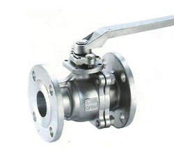
Q341F Soft sealed flange floating ball valve
Performance parameters
◎design standards: API 608、ISO17292、BS 5351、GB/T 12237◎Nominal diameter: DN25-200mm (1"-8")
◎Nominal pressure: PN16-PN150 (CL150- CL 900)
◎Flange standard:ASME B16.5、ASME B16.47、MSS SP 44、EN1092、ISO7005、GOST12815
◎Connection: flange, butt welding
◎Material range: carbon steel, alloy steel, stainless steel, duplex steel, titanium alloy
◎Sealing material:PTFE、RPTFE、PEEK、NYLON、MOLON、DELON
◎Operation: handle, worm, electric, pneumatic, gas-liquid linkage, electro-hydraulic linkage
◎temperature range:-46-200℃
◎Applicable medium: water, oil, gas, acid and other corrosive media main advantages
◎Fire protection design
◎Anti-static design
◎Design of stem anti - blowout
◎Low torque, low flow resistance
◎Low leakage fillers
Product appearance

| NPS | DN | L | d | D | D1 | D2 | b | f | Z-Φd | W | H | WT | W | H | WT | ||
| RF | RJ | BW | Manual | Worm gear | |||||||||||||
| 1/2 | 15 | 108 | 119 | 140 | 14 | 90 | 60.3 | 34.9 | 11.6 | 2 | 4-15 | 140 | 85 | 3 | / | / | / |
| 3/4 | 20 | 117 | 130 | 152 | 19 | 100 | 69.9 | 42.9 | 13.2 | 4-15 | 140 | 90 | 4 | / | / | / | |
| 1 | 25 | 127 | 140 | 165 | 25 | 110 | 79.4 | 50.8 | 14.7 | 4-15 | 150 | 99 | 5 | / | / | / | |
| 11/4 | 32 | 140 | 153 | 178 | 32 | 115 | 88.9 | 63.5 | 16.3 | 4-15 | 180 | 105 | 7 | / | / | / | |
| 11/2 | 40 | 165 | 178 | 190 | 38 | 125 | 98.4 | 73 | 17.9 | 4-15 | 200 | 126 | 8 | / | / | / | |
| 2 | 50 | 178 | 191 | 216 | 51 | 150 | 120.7 | 92.1 | 19.5 | 4-19 | 250 | 140 | 12 | / | / | / | |
| 21/2 | 65 | 190 | 203 | 241 | 64 | 180 | 139.7 | 104.8 | 22.7 | 4-19 | 300 | 165 | 18 | / | / | / | |
| 3 | 80 | 203 | 216 | 282 | 76 | 190 | 152.4 | 127 | 24.3 | 4-19 | 350 | 178 | 24 | / | / | / | |
| 4 | 100 | 229 | 242 | 305 | 102 | 230 | 190.5 | 157.2 | 24.3 | 8-19 | 500 | 230 | 38 | 305 | 380 | 53 | |
| 5 | 125 | 356 | 369 | 356 | 127 | 255 | 215.9 | 185.7 | 24.3 | 8-22 | 800 | 280 | 60 | 305 | 405 | 79 | |
| 6 | 150 | 394 | 407 | 457 | 152 | 280 | 241.3 | 215.9 | 25.9 | 8-22 | 800 | 310 | 82 | 305 | 460 | 102 | |
| 8 | 200 | 457 | 470 | 521 | 203 | 345 | 298.5 | 269.9 | 29 | 8-22 | 1000 | 350 | 145 | 305 | 550 | 185 | |
| 10 | 250 | 533 | 546 | 559 | 254 | 405 | 362 | 323.8 | 30.6 | 12-25 | / | / | / | 400 | 706 | 280 | |
Note: The above API standard design, flange size in accordance with ASME B16.5 standard. If you have different needs, can be customized according to demand.
Connection dimensions Q341F-300 1/2"~8"
|
NPS |
DN | L | d | D | D1 | D2 | b | f | Z-Φd | W | H | WT | W | H | WT | ||
| RF | RJ | BW | Manual | Worm gear | |||||||||||||
| 1/2 | 15 | 140 | 151 | 140 | 14 | 95 | 66.7 | 34.9 | 14.7 | 2 | 4-16 | 140 | 85 | 3 | / | / | / |
| 3/4 | 20 | 152 | 165 | 152 | 19 | 115 | 82.6 | 42.9 | 16.3 | 4-19 | 140 | 90 | 5 | / | / | / | |
| 1 | 25 | 165 | 178 | 165 | 25 | 125 | 88.9 | 50.8 | 17.9 | 4-19 | 150 | 99 | 6 | / | / | / | |
| 11/4 | 32 | 178 | 191 | 178 | 32 | 135 | 98.4 | 63.5 | 19.5 | 4-19 | 180 | 105 | 8 | / | / | / | |
| 11/2 | 40 | 190 | 203 | 190 | 38 | 155 | 114.3 | 73 | 21.1 | 4-22 | 200 | 126 | 11 | / | / | / | |
| 2 | 50 | 216 | 232 | 216 | 51 | 165 | 127 | 92.1 | 22.7 | 8-19 | 250 | 142 | 16 | / | / | / | |
| 21/2 | 65 | 241 | 257 | 241 | 64 | 190 | 149.2 | 104.8 | 24.9 | 8-22 | 300 | 165 | 24 | / | / | / | |
| 3 | 80 | 283 | 299 | 282 | 76 | 210 | 168.3 | 127 | 29 | 8-22 | 320 | 178 | 34 | / | 330 | 52 | |
| 4 | 100 | 305 | 321 | 305 | 102 | 255 | 200 | 157.2 | 32.2 | 8-22 | 500 | 230 | 56 | 305 | 380 | 76 | |
| 5 | 125 | 381 | 397 | 400 | 127 | 280 | 235 | 185.7 | 35.4 | 8-22 | 800 | 280 | 86 | 305 | 420 | 124 | |
| 6 | 150 | 403 | 419 | 457 | 152 | 320 | 269.9 | 215.9 | 37 | 12-22 | 800 | 310 | 125 | 305 | 480 | 163 | |
| 8 | 200 | 502 | 518 | 521 | 203 | 380 | 330.2 | 269.9 | 41.7 | 12-25 | 1000 | 350 | 222 | 305 | 560 | 267 | |
Note: The above API standard design, flange size in accordance with ASME B16.5 standard. If you have different needs, can be customized according to demand.
Connection dimensions Q341F-600 1/2"~4"
|
NPS |
DN | L | d | D | D1 | D2 | b | f | Z-Φd | W | H | WT | W | H | WT | ||
| RF | RJ | BW | Manual | Worm gear | |||||||||||||
| 1/2 | 15 | 165 | 165 | 165 | 14 | 95 | 66.7 | 34.9 | 21.3 | 7 | 4-16 | 140 | 79 | 5 | / | / | / |
| 3/4 | 20 | 190 | 190 | 190 | 19 | 115 | 82.6 | 42.9 | 22.9 | 4-19 | 140 | 83 | 7 | / | / | / | |
| 1 | 25 | 216 | 216 | 216 | 25 | 125 | 88.9 | 50.8 | 24.5 | 4-19 | 200 | 114 | 9 | / | / | / | |
| 11/4 | 32 | 229 | 229 | 229 | 32 | 135 | 98.4 | 63.5 | 27.7 | 4-19 | 200 | 120 | 13 | / | / | / | |
| 11/2 | 40 | 241 | 241 | 241 | 38 | 155 | 114.3 | 73 | 29.3 | 4-22 | 250 | 125 | 17 | / | / | / | |
| 2 | 50 | 292 | 295 | 292 | 51 | 165 | 127 | 92.1 | 32.4 | 8-19 | 300 | 156 | 25 | / | / | / | |
| 21/2 | 65 | 330 | 333 | 330 | 64 | 190 | 149.2 | 104.8 | 35.6 | 8-22 | 350 | 172 | 42 | / | / | / | |
| 3 | 80 | 356 | 359 | 356 | 76 | 210 | 168.3 | 127 | 38.8 | 8-22 | 500 | 220 | 56 | 305 | 370 | 76 | |
| 4 | 100 | 432 | 435 | 432 | 102 | 275 | 215.9 | 157.2 | 45.1 | 8-25 | 650 | 250 | 85 | 305 | 400 | 123 | |
Note: The above API standard design, flange size in accordance with ASME B16.5 standard. If you have different needs, can be customized according to demand.
Connection dimensions Q341F-900 1/2"~2"
|
NPS |
DN | L | d | D | D1 | D2 | b | f | Z-Φd | W | H | WT | W | H | WT | ||
| RF | RJ | BW | Manual | Worm gear | |||||||||||||
| 1/2 | 15 | 216 | 216 | 216 | 14 | 95 | 120 | 34.9 | 29.3 | 7 | 4-19 | 150 | 98 | 9 | / | / | / |
| 3/4 | 20 | 229 | 229 | 229 | 19 | 115 | 130 | 42.9 | 32.4 | 4-19 | 150 | 1005 | 13 | / | / | / | |
| 1 | 25 | 254 | 254 | 254 | 25 | 125 | 150 | 50.8 | 35.6 | 4-22 | 200 | 110 | 16 | / | / | / | |
| 11/4 | 32 | 279 | 279 | 279 | 32 | 135 | 160 | 63.5 | 35.6 | 4-22 | 250 | 120 | 24 | / | / | / | |
| 11/2 | 40 | 305 | 305 | 305 | 38 | 155 | 180 | 73 | 38.8 | 4-25 | 250 | 125 | 31 | / | / | / | |
| 2 | 50 | 368 | 371 | 368 | 51 | 165 | 215 | 92.1 | 45.1 | 8-22 | 350 | 160 | 45 | / | / | / | |
Note: The above API standard design, flange size in accordance with ASME B16.5 standard. If you have different needs, can be customized according to demand.
Connection dimensions Q341F-1500 1/2"~2"
|
NPS |
DN | L | d | D | D1 | D2 | b | f | Z-Φd | W | H | WT | W | H | WT | ||
| RF | RJ | BW | Manual | Worm gear | |||||||||||||
| 1/2 | 15 | 216 | 216 | 216 | 14 | 95 | 120 | 34.9 | 29.3 | 7 | 4-19 | 182 | 98 | 10 | / | / | / |
| 3/4 | 20 | 229 | 229 | 229 | 19 | 115 | 130 | 42.9 | 32.4 | 4-19 | 200 | 105 | 14 | / | / | / | |
| 1 | 25 | 254 | 254 | 254 | 25 | 125 | 150 | 50.8 | 35.6 | 4-22 | 250 | 110 | 17 | / | / | / | |
| 11/4 | 32 | 279 | 279 | 279 | 32 | 135 | 160 | 63.5 | 35.6 | 4-22 | 300 | 120 | 25 | / | / | / | |
| 11/2 | 40 | 305 | 305 | 305 | 38 | 155 | 180 | 73 | 38.8 | 4-25 | 350 | 130 | 33 | / | / | / | |
| 2 | 50 | 368 | 371 | 368 | 51 | 165 | 215 | 92.1 | 45.1 | 8-22 | 500 | 160 | 48 | / | / | / | |
Q341Y Metal Sealing Flange Floating Ball Valve

◎design standards: API 608,API 6D,ISO17292,ISO 14313, BS 5351
◎Nominal diameter: DN50-800mm (2"-32")
◎Nominal pressure: PN16-PN420 (CL150- CL2500)
◎Flange standard: ASME B16.5、ASME B16.47、MSS SP 44、EN1092、ISO7005、GOST12815
◎Material range: Carbon steel, alloy steel, stainless steel, duplex steel, titanium alloy
◎Seat Material: Surfacing WC\CrC\STELLITE\Fslloy
◎Ball Seal Material: Supersonic spraying WC\CrC\STELLITE\Fslloy
◎Operation method: Handle, worm gear, electric, pneumatic, gas-liquid linkage, electro-hydraulic linkage
◎temperature range: -46-750℃
◎Applicable medium: water, oil, gas, acid and other corrosive, high temperature and with particles, pool solid liquid medium
main feature
◎Valve seat and spherical sprayed tungsten carbide◎Design of stem anti - blowout
◎Double block double row
◎The cavity automatically pressure relief
Main profile and main connection dimensions Connection dimensions Q341Y-150 1/2"~10"
| NPS | DN | L | d | D | D1 | D2 | b | f | Z-Φd | W | H | WT | W | H | WT | ||
| RF | RJ | BW | Manual | Worm gear | |||||||||||||
| 1/2 | 15 | 108 | 119 | 140 | 14 | 90 | 60.3 | 34.9 | 11.6 | 2 | 4-15 | 140 | 85 | 3 | / | / | / |
| 3/4 | 20 | 117 | 130 | 152 | 19 | 100 | 69.9 | 42.9 | 13.2 | 4-15 | 140 | 90 | 4 | / | / | / | |
| 1 | 25 | 127 | 140 | 165 | 25 | 110 | 79.4 | 50.8 | 14.7 | 4-15 | 150 | 99 | 5 | / | / | / | |
| 11/4 | 32 | 140 | 153 | 178 | 32 | 115 | 88.9 | 63.5 | 16.3 | 4-15 | 180 | 105 | 7 | / | / | / | |
| 11/2 | 40 | 165 | 178 | 190 | 38 | 125 | 98.4 | 73 | 17.9 | 4-15 | 200 | 126 | 8 | / | / | / | |
| 2 | 50 | 178 | 191 | 216 | 51 | 150 | 120.7 | 92.1 | 19.5 | 4-19 | 250 | 140 | 12 | / | / | / | |
| 21/2 | 65 | 190 | 203 | 241 | 64 | 180 | 139.7 | 104.8 | 22.7 | 4-19 | 300 | 165 | 18 | / | / | / | |
| 3 | 80 | 203 | 216 | 282 | 76 | 190 | 152.4 | 127 | 24.3 | 4-19 | 350 | 178 | 24 | / | / | / | |
| 4 | 100 | 229 | 242 | 305 | 102 | 230 | 190.5 | 157.2 | 24.3 | 8-19 | 500 | 230 | 38 | 305 | 380 | 53 | |
| 5 | 125 | 356 | 369 | 356 | 127 | 255 | 215.9 | 185.7 | 24.3 | 8-22 | 800 | 280 | 60 | 305 | 405 | 79 | |
| 6 | 150 | 394 | 407 | 457 | 152 | 280 | 241.3 | 215.9 | 25.9 | 8-22 | 800 | 310 | 82 | 305 | 460 | 102 | |
| 8 | 200 | 457 | 470 | 521 | 203 | 345 | 298.5 | 269.9 | 29 | 8-22 | 1000 | 350 | 145 | 305 | 550 | 185 | |
| 10 | 250 | 533 | 546 | 559 | 254 | 405 | 362 | 323.8 | 30.6 | 12-25 | / | / | / | 400 | 706 | 280 | |
Note: The above API standard design, flange size in accordance with ASME B16.5 standard. If you have different needs, can be customized according to demand.
Connection dimensions Q341Y-300 1/2"~8"
| NPS | DN | L | d | D | D1 | D2 | b | f | Z-Φd | W | H | WT | W | H | WT | ||
| RF | RJ | BW | Manual | Worm gear | |||||||||||||
| 1/2 | 15 | 140 | 151 | 140 | 14 | 95 | 66.7 | 34.9 | 14.7 | 2 | 4-16 | 140 | 85 | 3 | / | / | / |
| 3/4 | 20 | 152 | 165 | 152 | 19 | 115 | 82.6 | 42.9 | 16.3 | 4-19 | 140 | 90 | 5 | / | / | / | |
| 1 | 25 | 165 | 178 | 165 | 25 | 125 | 88.9 | 50.8 | 17.9 | 4-19 | 150 | 99 | 6 | / | / | / | |
| 11/4 | 32 | 178 | 191 | 178 | 32 | 135 | 98.4 | 63.5 | 19.5 | 4-19 | 180 | 105 | 8 | / | / | / | |
| 11/2 | 40 | 190 | 203 | 190 | 38 | 155 | 114.3 | 73 | 21.1 | 4-22 | 200 | 126 | 11 | / | / | / | |
| 2 | 50 | 216 | 232 | 216 | 51 | 165 | 127 | 92.1 | 22.7 | 8-19 | 250 | 142 | 16 | / | / | / | |
| 21/2 | 65 | 241 | 257 | 241 | 64 | 190 | 149.2 | 104.8 | 24.9 | 8-22 | 300 | 165 | 24 | / | / | / | |
| 3 | 80 | 283 | 299 | 282 | 76 | 210 | 168.3 | 127 | 29 | 8-22 | 320 | 178 | 34 | / | 330 | 52 | |
| 4 | 100 | 305 | 321 | 305 | 102 | 255 | 200 | 157.2 | 32.2 | 8-22 | 500 | 230 | 56 | 305 | 380 | 76 | |
| 5 | 125 | 381 | 397 | 400 | 127 | 280 | 235 | 185.7 | 35.4 | 8-22 | 800 | 280 | 86 | 305 | 420 | 124 | |
| 6 | 150 | 403 | 419 | 457 | 152 | 320 | 269.9 | 215.9 | 37 | 12-22 | 800 | 310 | 125 | 305 | 480 | 163 | |
| 8 | 200 | 502 | 518 | 521 | 203 | 380 | 330.2 | 269.9 | 41.7 | 12-25 | 1000 | 350 | 222 | 305 | 560 | 267 | |
Note: The above API standard design, flange size in accordance with ASME B16.5 standard. If you have different needs, can be customized according to demand.
Connection dimensions Q341Y-600 1/2"~4"
| NPS | DN | L | d | D | D1 | D2 | b | f | Z-Φd | W | H | WT | W | H | WT | ||
| RF | RJ | BW | Manual | Worm gear | |||||||||||||
| 1/2 | 15 | 165 | 165 | 165 | 14 | 95 | 66.7 | 34.9 | 21.3 | 7 | 4-16 | 140 | 79 | 5 | / | / | / |
| 3/4 | 20 | 190 | 190 | 190 | 19 | 115 | 82.6 | 42.9 | 22.9 | 4-19 | 140 | 83 | 7 | / | / | / | |
| 1 | 25 | 216 | 216 | 216 | 25 | 125 | 88.9 | 50.8 | 24.5 | 4-19 | 200 | 114 | 9 | / | / | / | |
| 11/4 | 32 | 229 | 229 | 229 | 32 | 135 | 98.4 | 63.5 | 27.7 | 4-19 | 200 | 120 | 13 | / | / | / | |
| 11/2 | 40 | 241 | 241 | 241 | 38 | 155 | 114.3 | 73 | 29.3 | 4-22 | 250 | 125 | 17 | / | / | / | |
| 2 | 50 | 292 | 295 | 292 | 51 | 165 | 127 | 92.1 | 32.4 | 8-19 | 300 | 156 | 25 | / | / | / | |
| 21/2 | 65 | 330 | 333 | 330 | 64 | 190 | 149.2 | 104.8 | 35.6 | 8-22 | 350 | 172 | 42 | / | / | / | |
| 3 | 80 | 356 | 359 | 356 | 76 | 210 | 168.3 | 127 | 38.8 | 8-22 | 500 | 220 | 56 | 305 | 370 | 76 | |
| 4 | 100 | 432 | 435 | 432 | 102 | 275 | 215.9 | 157.2 | 45.1 | 8-25 | 650 | 250 | 85 | 305 | 400 | 123 | |
Note: The above API standard design, flange size in accordance with ASME B16.5 standard. If you have different needs, can be customized according to demand.
Connection dimensions Q341Y-900 1/2"~2"
| NPS | DN | L | d | D | D1 | D2 | b | f | Z-Φd | W | H | WT | W | H | WT | ||
| RF | RJ | BW | Manual | Worm gear | |||||||||||||
| 1/2 | 15 | 216 | 216 | 216 | 14 | 95 | 120 | 34.9 | 29.3 | 7 | 4-19 | 150 | 98 | 9 | / | / | / |
| 3/4 | 20 | 229 | 229 | 229 | 19 | 115 | 130 | 42.9 | 32.4 | 4-19 | 150 | 1005 | 13 | / | / | / | |
| 1 | 25 | 254 | 254 | 254 | 25 | 125 | 150 | 50.8 | 35.6 | 4-22 | 200 | 110 | 16 | / | / | / | |
| 11/4 | 32 | 279 | 279 | 279 | 32 | 135 | 160 | 63.5 | 35.6 | 4-22 | 250 | 120 | 24 | / | / | / | |
| 11/2 | 40 | 305 | 305 | 305 | 38 | 155 | 180 | 73 | 38.8 | 4-25 | 250 | 125 | 31 | / | / | / | |
| 2 | 50 | 368 | 371 | 368 | 51 | 165 | 215 | 92.1 | 45.1 | 8-22 | 350 | 160 | 45 | / | / | / | |
Note: The above API standard design, flange size in accordance with ASME B16.5 standard. If you have different needs, can be customized according to demand.
Connection dimensions Q341Y-1500 1/2"~2"
| NPS | DN | L | d | D | D1 | D2 | b | f | Z-Φd | W | H | WT | W | H | WT | ||
| RF | RJ | BW | Manual | Worm gear | |||||||||||||
| 1/2 | 15 | 216 | 216 | 216 | 14 | 95 | 120 | 34.9 | 29.3 | 7 | 4-19 | 182 | 98 | 10 | / | / | / |
| 3/4 | 20 | 229 | 229 | 229 | 19 | 115 | 130 | 42.9 | 32.4 | 4-19 | 200 | 105 | 14 | / | / | / | |
| 1 | 25 | 254 | 254 | 254 | 25 | 125 | 150 | 50.8 | 35.6 | 4-22 | 250 | 110 | 17 | / | / | / | |
| 11/4 | 32 | 279 | 279 | 279 | 32 | 135 | 160 | 63.5 | 35.6 | 4-22 | 300 | 120 | 25 | / | / | / | |
| 11/2 | 40 | 305 | 305 | 305 | 38 | 155 | 180 | 73 | 38.8 | 4-25 | 350 | 130 | 33 | / | / | / | |
| 2 | 50 | 368 | 371 | 368 | 51 | 165 | 215 | 92.1 | 45.1 | 8-22 | 500 | 160 | 48 | / | / | / | |
DQ41F Cryogenic Soft Sealing Flange Floating Ball Valve

Performance parameters
◎design standards: API 6D、API 608、ISO 17292、ISO 14723、ISO 14313、BS6364
◎Nominal diameter: DN25-800mm (1"-32")
◎Nominal pressure: PN16-PN260 (CL150- CL1500)
◎Connecting flange: ASME B16.5、ASME 16.47、EN1092、ISO7005、GOST12815
◎Material: low temperature steel, stainless steel
◎Sealing material: PTFE、RPTFE、PCTFE
◎Operation: handle, worm, electric, pneumatic, gas-liquid linkage, electro-hydraulic linkage
◎temperature range: -196-200℃
◎Applicable medium: Ethylene, propylene, liquefied natural gas and the like
main feature
◎Fire protection design
◎Anti-static design
◎Design of stem anti - blowout
◎Pressure relief valve automatically discharge valve chamber pressure
◎Cryogenic valve stuffing box elevation design, the filler away from the low-temperature area, the maximum protection of the filler at the low-leakage seal.
◎The valve assembly is subjected to cryogenic cryogenic treatment
Main profile and main connection dimensions
| model | temperature | -46℃ | -101℃ | -196℃ | |
| specification | size(mm) | ||||
| NPS | DN | Neck length H | |||
|
DQ41F DQ61F DQ347F DQ367F -150/300 /600/900 |
1/2 | 15 | 60 | 100 | 200 |
| 1 | 25 | 60 | 100 | 200 | |
| 1 1/2 | 40 | 80 | 125 | 250 | |
| 2 | 50 | 80 | 125 | 250 | |
| 3 | 80 | 90 | 150 | 300 | |
| 4 | 100 | 90 | 150 | 300 | |
| 6 | 150 | 100 | 175 | 350 | |
| 8 | 200 | 100 | 175 | 350 | |
| 10 | 250 | 100 | 200 | 400 | |
| 12 | 300 | 100 | 200 | 400 | |
| 14 | 350 | 110 | 250 | 450 | |
| 16 | 400 | 110 | 250 | 450 | |
| 18 | 450 | 110 | 300 | 500 | |
| 24 | 600 | 110 | 300 | 500 | |
| 28 | 700 | 110 | 350 | 550 | |
| 32 | 800 | 110 | 350 | 550 | |
| 36 | 900 | 120 | 400 | 600 | |
| 48 | 1000 | 120 | 400 | 600 | |
Connection dimensions Q41F/ Q61F -150 1/2"~3"
| NPS | DN | L | d | D | D1 | D2 | b | f | Z-Φd | W | H | ||||
| RF | RJ | BW | -46℃ | -101℃ | -196℃ | ||||||||||
| 1/2 | 15 | 108 | 119 | 140 | 14 | 90 | 60.3 | 34.9 | 11.6 | 2 | 4-15 | 140 | 145 | 185 | 285 |
| 1 | 25 | 127 | 140 | 165 | 25 | 110 | 79.4 | 50.8 | 14.7 | 4-15 | 150 | 159 | 199 | 299 | |
| 11/2 | 40 | 165 | 178 | 190 | 38 | 125 | 98.4 | 73 | 17.9 | 4-15 | 200 | 206 | 301 | 376 | |
| 2 | 50 | 178 | 191 | 216 | 51 | 150 | 120.7 | 92.1 | 19.5 | 4-19 | 250 | 320 | 265 | 390 | |
| 3 | 80 | 203 | 216 | 282 | 76 | 190 | 152.4 | 127 | 24.3 | 4-19 | 350 | 268 | 328 | 478 | |
Note: The above API standard design, flange size in accordance with ASME B16.5 standard. If you have different needs, can be customized according to demand.
Connection dimensions Q41F/ Q61F -300 1/2"~3"
| NPS | DN | L | d | D | D1 | D2 | b | f | Z-Φd | W | H | ||||
| RF | RJ | BW | -46℃ | -101℃ | -196℃ | ||||||||||
| 1/2 | 15 | 140 | 151 | 140 | 14 | 95 | 66.7 | 34.9 | 14.7 | 2 | 4-16 | 140 | 145 | 185 | 285 |
| 1 | 25 | 165 | 178 | 165 | 25 | 125 | 88.9 | 50.8 | 17.9 | 4-19 | 150 | 159 | 199 | 299 | |
| 11/2 | 40 | 190 | 203 | 190 | 38 | 155 | 114.3 | 73 | 21.1 | 4-22 | 200 | 206 | 249 | 376 | |
| 2 | 50 | 216 | 232 | 216 | 51 | 165 | 127 | 92.1 | 22.7 | 8-19 | 250 | 222 | 267 | 392 | |
| 3 | 80 | 283 | 299 | 282 | 76 | 210 | 168.3 | 127 | 29 | 8-22 | 320 | 268 | 328 | 478 | |
Note: The above API standard design, flange size in accordance with ASME B16.5 standard. If you have different needs, can be customized according to demand.
Connection dimensions Q41F/ Q61F -300 1/2"~2 1/2"
| NPS | DN | L | d | D | D1 | D2 | b | f | Z-Φd | W | H | ||||
| RF | RJ | BW | -46℃ | -101℃ | -196℃ | ||||||||||
| 1/2 | 15 | 165 | 165 | 165 | 14 | 95 | 66.7 | 34.9 | 21.3 | 7 | 4-16 | 140 | 139 | 179 | 279 |
| 1 | 25 | 216 | 216 | 216 | 25 | 125 | 88.9 | 50.8 | 24.5 | 4-19 | 200 | 174 | 214 | 314 | |
| 11/2 | 40 | 241 | 241 | 241 | 38 | 155 | 114.3 | 73 | 29.3 | 4-22 | 250 | 205 | 250 | 375 | |
| 2 | 50 | 292 | 295 | 292 | 51 | 165 | 127 | 92.1 | 32.4 | 8-19 | 300 | 236 | 281 | 406 | |
| 21/2 | 65 | 330 | 333 | 330 | 64 | 190 | 149.2 | 104.8 | 35.6 | 8-22 | 350 | 252 | 297 | 422 | |

Performance parameters
◎design standards: API 6D、API 608、GB/T 12237、ISO 17292、ISO 14313
◎Nominal diameter: DN50-1500mm (2"-60")
◎Nominal pressure: PN10-PN420 (150LB-2500LB)
◎Connection Standard: ASME B16.5、GB/T 9113.1、JB/T79.1~4
◎Connection method: RF、FTJ、BW
◎Material range: carbon steel, low carbon steel
◎Sealing material: PTFE、RPTFE、PEEK、NYLON、MOLON、DELON
◎Operation: handle, worm, electric, pneumatic, gas-liquid linkage, electro-hydraulic linkage
◎temperature range: -60~+200℃
◎Applicable medium: Water, oil, natural gas and so on
main feature
◎Simple structure, good sealing performance, small torque
◎All welded body, diameter reduction and diameter structure with the lowest flow resistance design
◎Emergency grease injection structure
◎In the cavity automatic pressure relief design
◎low leakage filler
◎anti-Fire, anti-static, anti-stem anti-spray design
◎Valve seat function: double block double row, while the piston, while automatic pressure relief, both sides of the piston
◎Extended valve stem, valve cover structure, ground or buried installation
| NPS | L | d | D | D1 | D2 | b | f | Z-Φd | H | WT(Kg) | |||
| RF | BW | RTJ | BW | RF | |||||||||
| 6 | 394 | 457 | 406 | 152 | 280 | 241.3 | 215.9 | 25.9 | 2 | 8-22 | 225 | 185 | 220 |
| 8 | 457 | 521 | 470 | 203 | 345 | 298.5 | 269.9 | 29 | 8-22 | 258 | 250 | 290 | |
| 10 | 533 | 559 | 546 | 254 | 405 | 362 | 323.8 | 30.6 | 12-25 | 310 | 400 | 430 | |
| 12 | 610 | 635 | 622 | 305 | 485 | 431.8 | 381 | 32.2 | 12-25 | 350 | 550 | 620 | |
| 14 | 686 | 762 | 699 | 337 | 535 | 476.3 | 412.8 | 35.4 | 12-29 | 382 | 820 | 900 | |
| 16 | 762 | 838 | 775 | 387 | 595 | 539.8 | 469.9 | 37 | 16-29 | 421 | 1100 | 1220 | |
| 18 | 864 | 914 | 876 | 438 | 635 | 577.9 | 533.4 | 40.1 | 16-32 | 468 | 1400 | 1550 | |
| 20 | 914 | 991 | 927 | 489 | 700 | 635 | 584.2 | 43.3 | 20-32 | 510 | 1750 | 1950 | |
| 24 | 1067 | 1143 | 1080 | 591 | 815 | 749.3 | 692.2 | 48.1 | 20-35 | 592 | 2800 | 3050 | |
| 26 | 1143 | 1245 | / | 633 | 785 | 744.5 | 711 | 44 | 36-22 | 635 | 2900 | 3250 | |
| 28 | 1245 | 1346 | / | 684 | 835 | 795.5 | 762 | 47 | 40-22 | 675 | 3400 | 3700 | |
| 30 | 1295 | 1397 | / | 735 | 885 | 846.1 | 813 | 47 | 44-22 | 723 | 4800 | 5300 | |
| 32 | 1372 | 1524 | / | 779 | 940 | 900.1 | 864 | 49 | 48-22 | 751 | 5500 | 6000 | |
| 36 | 1524 | 1727 | / | 874 | 1055 | 1009.6 | 972 | 55 | 44-26 | 858 | 7550 | 8370 | |
Note: The above API standard design, flange size in accordance with ASME B16.5 / B16.47 standard. If you have different needs, can be customized according to demand.
Connection dimensions Q347F/ Q367F -300 6"~36"
| NPS | L | d | D | D1 | D2 | b | f | Z-Φd | H | WT(Kg) | |||
| RF | BW | RTJ | BW | RF | |||||||||
| 6 | 403 | 457 | 419 | 152 | 320 | 269.9 | 215.9 | 37 | 2 | 12-22 | 225 | 185 | 230 |
| 8 | 502 | 521 | 518 | 203 | 380 | 330.2 | 269.9 | 41.7 | 12-25 | 258 | 250 | 300 | |
| 10 | 568 | 559 | 584 | 254 | 445 | 387.4 | 323.8 | 48.1 | 16-29 | 310 | 400 | 460 | |
| 12 | 648 | 635 | 664 | 305 | 520 | 450.8 | 381 | 51.3 | 16-32 | 350 | 550 | 670 | |
| 14 | 762 | 762 | 778 | 337 | 585 | 514.4 | 412.8 | 54.4 | 20-32 | 382 | 820 | 1000 | |
| 16 | 838 | 838 | 854 | 387 | 650 | 571.5 | 469.9 | 57.6 | 20-35 | 421 | 1100 | 1320 | |
| 18 | 914 | 914 | 930 | 432 | 710 | 628.6 | 533.4 | 60.8 | 24-35 | 468 | 1400 | 1650 | |
| 20 | 991 | 991 | 1010 | 483 | 775 | 685.8 | 584.2 | 64 | 24-35 | 510 | 1750 | 2000 | |
| 24 | 1143 | 1143 | 1165 | 584 | 915 | 812.8 | 692.2 | 70.3 | 24-41 | 592 | 1800 | 2550 | |
| 26 | 1245 | 1245 | / | 633 | 865 | 803.5 | 737 | 87.5 | 32-35.5 | 635 | 1900 | 3300 | |
| 28 | 1346 | 1346 | / | 684 | 920 | 857.2 | 787 | 87.5 | 36-35.5 | 675 | 3400 | 3750 | |
| 30 | 1397 | 1397 | / | 735 | 990 | 920.8 | 845 | 93 | 3639 | 723 | 4800 | 5500 | |
| 32 | 1524 | 1524 | / | 779 | 1055 | 978 | 953 | 102 | 32-42 | 751 | 5500 | 6500 | |
| 36 | 1727 | 1727 | / | 874 | 1170 | 1089 | 1010 | 102 | 32-45 | 858 | 7890 | 8800 | |
Note: The above API standard design, flange size in accordance with ASME B16.5 / B16.47 standard. If you have different needs, can be customized according to demand.
Connection dimensions Q347F/ Q367F -600 6"~24"
| NPS | L | d | D | D1 | D2 | b | f | Z-Φd | H | WT(Kg) | |||
| RF | BW | RTJ | BW | RF | |||||||||
| 6 | 559 | 559 | 562 | 150 | 355 | 292.1 | 215.9 | 54.7 | 7 | 12-29 | 255 | 250 | 330 |
| 8 | 660 | 660 | 664 | 201 | 420 | 349.2 | 269.9 | 62.6 | 12-32 | 290 | 340 | 450 | |
| 10 | 787 | 787 | 791 | 252 | 510 | 431.8 | 323.8 | 70.5 | 16-35 | 320 | 570 | 710 | |
| 12 | 838 | 838 | 841 | 303 | 560 | 489 | 381 | 73.7 | 20-35 | 380 | 850 | 1000 | |
| 14 | 889 | 889 | 892 | 334 | 605 | 527 | 412.8 | 76.9 | 20-38 | 410 | 1100 | 1370 | |
| 16 | 991 | 991 | 994 | 385 | 685 | 603.2 | 469.9 | 83.2 | 20-41 | 435 | 1350 | 1650 | |
| 18 | 1092 | 1092 | 1095 | 436 | 745 | 654 | 533.4 | 89.6 | 20-44 | 495 | 2100 | 2400 | |
| 20 | 1194 | 1194 | 1200 | 487 | 815 | 723.9 | 584.2 | 95.9 | 24-44 | 535 | 2600 | 3000 | |
| 24 | 1397 | 1397 | 1407 | 589 | 940 | 838.2 | 692.2 | 108.6 | 24-51 | 642 | 3700 | 4300 | |
Note: The above API standard design, flange size in accordance with ASME B16.5 standard. If you have different needs, can be customized according to demand.
Connection dimensions Q347F/ Q367F -900 6"~24"
| NPS | L | d | D | D1 | D2 | b | f | Z-Φd | H | WT(Kg) | |||
| RF | BW | RTJ | BW | RF | |||||||||
| 6 | 610 | 610 | 613 | 150 | 380 | 317.5 | 215.9 | 62.6 | 7 | 12-32 | 255 | 300 | 430 |
| 8 | 737 | 737 | 740 | 201 | 470 | 393.7 | 269.9 | 70.5 | 12-38 | 290 | 400 | 520 | |
| 10 | 838 | 838 | 841 | 252 | 545 | 469.9 | 323.8 | 76.9 | 16-38 | 320 | 640 | 820 | |
| 12 | 965 | 965 | 968 | 303 | 610 | 533.4 | 381 | 86.4 | 20-38 | 380 | 900 | 1050 | |
| 14 | 1029 | 1029 | 1039 | 334 | 640 | 558.8 | 412.8 | 92.8 | 20-41 | 410 | 1020 | 1400 | |
| 16 | 1130 | 1130 | 1140 | 385 | 705 | 616 | 469.9 | 95.9 | 20-44 | 435 | 1350 | 2050 | |
| 18 | 1219 | 1219 | 1232 | 436 | 785 | 685.8 | 533 | 109 | 20-51 | 495 | 2600 | 3400 | |
| 20 | 1321 | 1321 | 1334 | 487 | 855 | 749.3 | 584 | 115 | 20-54 | 535 | 3700 | 4200 | |
| 24 | 1549 | 1549 | 1568 | 589 | 1040 | 901.7 | 692 | 147 | 20-67 | 642 | 4400 | 5400 | |
Note: The above API standard design, flange size in accordance with ASME B16.5 standard. If you have different needs, can be customized according to demand.
Connection dimensions Q347F/ Q367F -1500 6"~14"
| NPS | L | d | D | D1 | D2 | b | f | Z-Φd | H | WT(Kg) | |||
| RF | BW | RTJ | BW | RF | |||||||||
| 6 | 705 | 705 | 711 | 144 | 395 | 317.5 | 215.9 | 89.6 | 7 | 12-38 | 255 | 375 | 565 |
| 8 | 832 | 832 | 842 | 192 | 485 | 393.7 | 269.9 | 99.1 | 12-45 | 290 | 415 | 505 | |
| 10 | 991 | 991 | 1001 | 239 | 585 | 482.6 | 323.8 | 115 | 12-51 | 320 | 525 | 640 | |
| 12 | 1130 | 1130 | 1146 | 287 | 675 | 571.5 | 381 | 130.9 | 16-54 | 380 | 780 | 950 | |
| 14 | 1257 | 1257 | 1276 | 315 | 750 | 635 | 416 | 140 | 16-60 | 410 | 1145 | 1380 | |
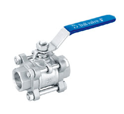
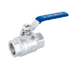
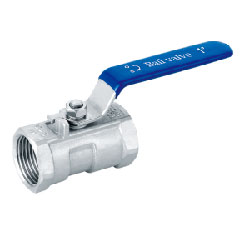
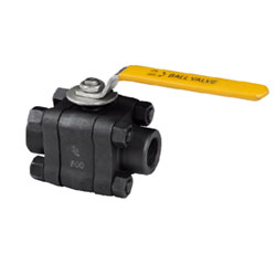
Q11F female thread ball valve connection
Performance parameters
◎design standards: API 6D GB/T 12224
◎Nominal diameter: DN15-100mm (1/2"-4")
◎Nominal pressure: PN10-PN40 (150LB-250LB)
◎Connection Standard: ASME B1.20.1、GB/T 7073、DIN 2999、ISO 7/1
◎Connection: thread, socket welding, butt welding
◎Material range: Carbon steel, alloy steel, stainless steel, duplex steel, titanium alloy
◎Sealing material: PTFE、RPTFE、PEEK、NYLON、MOLON、DELON
◎Operation method: Handle, worm gear, electric, pneumatic and so on
◎temperature range: -29-180℃
◎Applicable medium: Water, oil, gas, acid and other corrosive media
Main feature
◎stem blowout design
◎chamber pressure automatically pressure relief
◎low torque, low flow resistance
◎low leakage filler
◎lock device
Product appearance

Main profile and main connection dimensions
| Structure type | caliber | Rc | Size(mm) |
WT Kg |
||||
| DN | NPS | L | d | W | H | |||
|
Three-piece PN10~PN40 |
10 | 3/8 | 3/8 | 60 | 10 | 95 | 57 | 0.4 |
| 15 | 1/2 | 1/2 | 75 | 14 | 110 | 68 | 0.5 | |
| 20 | 3/4 | 3/4 | 80 | 19 | 110 | 70 | 0.7 | |
| 25 | 1 | 1 | 90 | 25 | 140 | 80 | 1.2 | |
| 32 | 1 1/4 | 1 1/4 | 110 | 32 | 140 | 85 | 1.9 | |
| 40 | 1 1/2 | 1 1/2 | 120 | 38 | 180 | 100 | 2.7 | |
| 50 | 2 | 2 | 144 | 50 | 180 | 110 | 3.9 | |
| 65 | 2 1/2 | 2 1/2 | 186 | 64 | 200 | 130 | 7.1 | |
| 80 | 3 | 3 | 206 | 76 | 250 | 150 | 11.5 | |
| 100 | 4 | 4 | 240 | 100 | 250 | 170 | 20.5 | |
| Two-piece PN10~PN40 | 10 | 3/8 | 3/8 | 55 | 10 | 95 | 57 | 0.3 |
| 15 | 1/2 | 1/2 | 65 | 14 | 110 | 68 | 0.4 | |
| 20 | 3/4 | 3/4 | 78 | 19 | 110 | 70 | 0.6 | |
| 25 | 1 | 1 | 88 | 25 | 140 | 80 | 1.0 | |
| 32 | 1 1/4 | 1 1/4 | 105 | 32 | 140 | 85 | 1.6 | |
| 40 | 1 1/2 | 1 1/2 | 112 | 38 | 180 | 100 | 2.3 | |
| 50 | 2 | 2 | 125 | 50 | 180 | 110 | 3.3 | |
| 65 | 2 1/2 | 2 1/2 | 165 | 64 | 200 | 130 | 6.0 | |
| 80 | 3 | 3 | 184 | 76 | 250 | 150 | 9.8 | |
|
One-piece |
10 | 3/8 | 3/8 | 39 | 6 | 70 | 35 | 0.2 |
| 15 | 1/2 | 1/2 | 57 | 9 | 95 | 44 | 0.3 | |
| 20 | 3/4 | 3/4 | 59 | 12 | 95 | 47 | 0.4 | |
| 25 | 1 | 1 | 71 | 16 | 110 | 55 | 0.6 | |
| 32 | 1 1/4 | 1 1/4 | 80 | 20 | 110 | 60 | 1.1 | |
| 40 | 1 1/2 | 1 1/2 | 83 | 25 | 140 | 75 | 1.5 | |
| 50 | 2 | 2 | 100 | 32 | 140 | 80 | 2.8 | |
Note: The above API standard design, thread size in accordance with ASME B1.20.1 standard. If you have different needs, can be customized according to demand.