Products
- Products
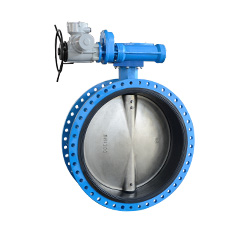
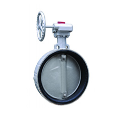
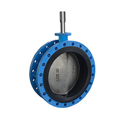
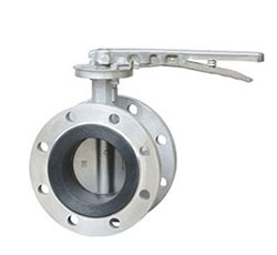
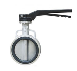
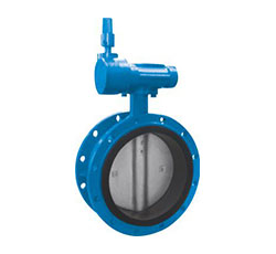
- Flange Type Concentric Rubber Lining Butterfly Valve
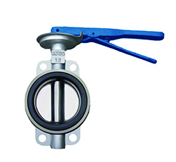
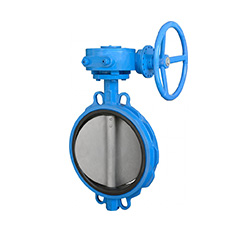
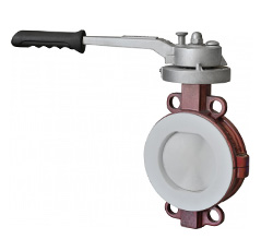
- Wafer Type Concentric Rubber Lining Butterfly Valve
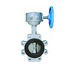
- Lug Type Concentric Rubber Lining Butterfly Valve
Contact us
Tel:+86-577-8682 5111
Email:zjbeize@163.com
Summary of Functions
Concentric rubber lined butterfly valve is a kind of valve with thick polymer lining on the body and disc. The lining makes the body completely isolate from medium and provides excellent anti-corrosive performance. It designs as a device to shut-off or regulate the working medium flow and installs in pipelines or vessels with medium of acid, alkali, salt and oxidant, reducing agent, organic solvent in chemical, petroleum, pharmacy, food, iron and steel smelting, paper making, water power plant etc. It can be served as gate valve, globe valves as well as other shutting off or regulating valves.
Products Features
1. Small dimensions and light weight, easy to disassembly and repair, can be installed in any position.
2. Simple and impact construction, quick open-close, small operation torque.
3. Excellent Bi-directional sealing function, Zero leakage in test.
4. Excellent medium isolation and regulating function, the flow curve tends to be straight line. Excellent regulation performance
5. Little medium is stocked in pipeline, strong anti-scouring ability , can be used for the harsh working environment
Construction Features
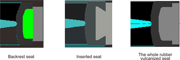
For this concentric butterfly valves, the center of disc sealing and the center of the shaft is coincident, for a certain amount of magnitude of interference, the sealed pressure ratio between the body seat and the disc sealing surface is created to make sure the good sealing performance of the valve.The seat of this concentric butterfly valve is elastic material such as rubber or Teflon material, and its usually used for low pressure pipeline.
The type of seat: Backrest seat, Inserted seat, the whole rubber vulcanized seat.
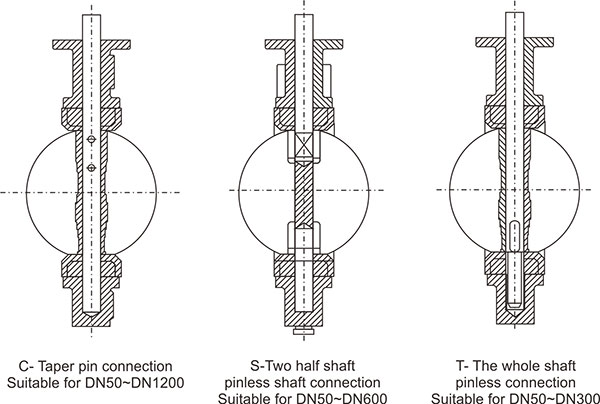
The connection between the disc and shaft: Taper pin connection, Two half shaft pinless shaft connection, The whole shaft pinless shaft.
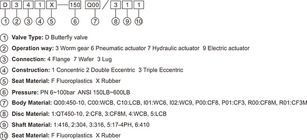
Model Designations
Standard
| Design & Manufacture | Flange Connection | Face to Face Dimension | Test & Inspection |
| GB/T 122238 | GB/T 9113 | GB/T 12221 | GB/T 13927 |
| API 609 | ASME B16.5 ASME B16.47 | API 609 ASME B16.10 | API 598 |
| EN 593 | EN 1092 | EN 558 | EN 12266-1 |
| ISO 10631 | ISO 7005 | ISO 5752 | ISO 5208 |
Scope of Application
Nominal Diameter: 2" ~ 48" (DN50~1200)
Nominal Pressure: 150LB PN6~16
Suitable Temperature: -29°C ~200°C
Connection: Wafer, Lug, Flange
Applicable Medium: fresh water, sea water, air, almost of the chemicals and all kinds of corrosive medium.
Part and Material
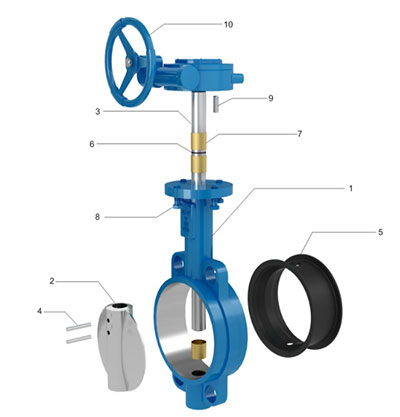
Basic configuration of Parts and Materials
| Item No. | Part Name | Material |
| 1 | Body | WCB/GGG40/C95800 |
| 2 | Disc | WCB/GGG40/C95800 |
| 3 | Shaft | 416 / 420 / 431 / 304 |
| 4 | Seat | 416 / 420 / 431 / 304 |
| 5 | Seat | EPDM / NBR/ VITON / PTFE |
| 6 | O-ring | EPDM / NBR/ VITON |
| 7 | Bushing | Bronze/PTFE |
| 8 | Studs | 8.8/B7/B8 |
| 9 | Key | 1045 |
| 10 | Subassembly | Subassembly |

Connection Dimensions D341X-16C DN50~DN1200
| DN | L | Flange Dimensions | Overall Dimensions |
The Dimensions of Top Flange |
Weight(Kg) | ||||||||||
| D | D1 | D2 | b | Z-Φ d | H0 | H | A | B | G | ISO 5211 | d0 | h | |||
| 50 | 108 | 165 | 125 | 102 | 18 | 4-Φ18 | 83 | 152 | 154 | 45 | 150 | F05 | 13 | 32 | 12 |
| 65 | 112 | 185 | 145 | 122 | 18 | 8-Φ18 | 93 | 162 | 154 | 45 | 150 | F05 | 13 | 32 | 13.5 |
| 80 | 114 | 200 | 160 | 138 | 20 | 8-Φ18 | 100 | 132 | 154 | 45 | 150 | F05 | 13 | 32 | 15 |
| 100 | 127 | 220 | 180 | 158 | 20 | 8-Φ18 | 114 | 187 | 154 | 45 | 150 | F07 | 16 | 32 | 17 |
| 125 | 140 | 250 | 210 | 188 | 22 | 8-Φ18 | 122 | 207 | 154 | 45 | 150 | F07 | 19 | 32 | 21 |
| 150 | 140 | 285 | 240 | 212 | 22 | 8-Φ22 | 143 | 222 | 154 | 45 | 150 | F07 | 19 | 32 | 27 |
| 200 | 152 | 340 | 295 | 268 | 24 | 12-Φ22 | 170 | 245 | 250 | 63 | 300 | F10 | 22 | 32 | 39 |
| 250 | 165 | 405 | 355 | 320 | 26 | 12-Φ26 | 198 | 275 | 250 | 63 | 300 | F10 | 29 | 32 | 55 |
| 300 | 178 | 460 | 410 | 378 | 28 | 12-Φ26 | 222 | 320 | 227 | 80 | 300 | F10 | 32 | 32 | 68 |
| 350 | 190 | 520 | 470 | 438 | 30 | 16-Φ26 | 267 | 350 | 227 | 80 | 300 | F12 | 32 | 32 | 82 |
| 400 | 216 | 580 | 525 | 490 | 32 | 16-Φ30 | 278 | 469 | 278 | 178 | 300 | F14 | 38 | 60 | 156 |
| 450 | 222 | 640 | 585 | 550 | 40 | 20-Φ30 | 320 | 504 | 278 | 178 | 300 | F14 | 43 | 60 | 210 |
| 500 | 229 | 715 | 650 | 610 | 44 | 20-Φ33 | 329 | 559 | 278 | 178 | 300 | F14 | 46 | 60 | 265 |
| 600 | 267 | 840 | 770 | 725 | 54 | 20-Φ36 | 384 | 645 | 200 | 304 | 300 | F16 | 54 | 70 | 305 |
| 700 | 292 | 910 | 840 | 795 | 40 | 24-Φ36 | 450 | 726 | 244 | 327 | 400 | F25 | 63 | 70 | 406 |
| 800 | 318 | 1025 | 950 | 900 | 42 | 24-Φ39 | 501 | 786 | 244 | 327 | 400 | F25 | 63 | 70 | 543 |
| 900 | 330 | 1125 | 1050 | 1000 | 44 | 28-Φ39 | 550 | 969 | 270 | 411 | 400 | F25 | 75 | 80 | 639 |
| 1000 | 410 | 1255 | 1170 | 1115 | 46 | 28-Φ42 | 622 | 1019 | 418 | 455 | 435 | F25 | 85 | 100 | 735 |
| 1200 | 470 | 1485 | 1390 | 1330 | 52 | 32-Φ48 | 763 | 1309 | 600 | 709 | 480 | F30 | 105 | 100 | 1474 |
Note:
1. The above dimensions are normal dimensions, and the flange dimensions are made according to EN 1092-1, but it also can be made according to different requirements.
2. For restricted by length, for inquired specifications not listed, please contact us.
3. The operation can be Worm gear , pneumatic actuator, electric actuator and hydraulic actuator, ect.

Connection Dimensions D371X-16C DN50~DN1200
| DN | L | Flange Dimensions | Overall Dimensions |
The Dimensions of Top Flange |
Weight(Kg) | |||||||||||
| D1 | D2 | Z-Φ d | 4-W | H0 | H | A | B | C | E | G | ISO 5211 | d0 | h | |||
| 50 | 43 | 125 | 102 | 4-Φ18 | --- | 73 | 145 | 52 | 45 | 150 | 52 | 150 | F05 | 13 | 32 | 5 |
| 65 | 46 | 145 | 122 | 8-Φ18 | --- | 80 | 152 | 52 | 45 | 150 | 52 | 150 | F05 | 13 | 32 | 5.3 |
| 80 | 46 | 160 | 138 | 8-Φ18 | --- | 88 | 159 | 52 | 45 | 150 | 52 | 150 | F05 | 13 | 32 | 6.45 |
| 100 | 52 | 180 | 158 | 8-Φ18 | --- | 103 | 179 | 52 | 45 | 150 | 52 | 150 | F07 | 16 | 32 | 7.65 |
| 125 | 56 | 210 | 188 | 8-Φ18 | --- | 116 | 192 | 52 | 45 | 150 | 52 | 150 | F07 | 19 | 32 | 8.85 |
| 150 | 56 | 240 | 212 | 8-Φ22 | --- | 138 | 208 | 52 | 45 | 150 | 52 | 150 | F07 | 19 | 32 | 12 |
| 200 | 60 | 295 | 268 | 12-Φ22 | --- | 162 | 240 | 75 | 63 | 300 | 75 | 300 | F10 | 22 | 32 | 22 |
| 250 | 68 | 355 | 320 | 12-Φ26 | --- | 202 | 284 | 75 | 63 | 300 | 75 | 300 | F10 | 29 | 32 | 28 |
| 300 | 78 | 410 | 378 | 12-Φ26 | --- | 222 | 315 | 81 | 80 | 300 | 81 | 300 | F10 | 32 | 32 | 39 |
| 350 | 78 | 470 | 438 | 16-Φ26 | --- | 270 | 355 | 81 | 80 | 300 | 81 | 300 | F12 | 32 | 32 | 58 |
| 400 | 102 | 525 | 490 | 16-Φ30 | --- | 244 | 424 | 121 | 178 | 300 | 115 | 300 | F14 | 38 | 60 | 103 |
| 450 | 114 | 585 | 550 | 20-Φ30 | --- | 349 | 495 | 121 | 178 | 300 | 115 | 300 | F14 | 43 | 60 | 112 |
| 500 | 127 | 650 | 610 | 20-Φ33 | --- | 387 | 472 | 121 | 178 | 300 | 115 | 300 | F14 | 46 | 60 | 155 |
| 600 | 154 | 770 | 725 | 20-Φ36 | --- | 463 | 558 | 145 | 304 | 300 | 144 | 300 | F16 | 54 | 70 | 228 |
| 700 | 165 | 840 | 795 | 24-Φ36 | --- | 524 | 786 | 183 | 327 | 244 | 189 | 400 | F25 | 63 | 32 | 397 |
| 800 | 190 | 950 | 900 | 24-Φ39 | --- | 608 | 832 | 183 | 327 | 244 | 189 | 400 | F25 | 63 | 32 | 487 |
| 900 | 200 | 1050 | 1000 | 24-Φ39 | 4-M36 | 656 | 1004 | 215 | 411 | 270 | 220 | 400 | F25 | 75 | 32 | 640 |
| 1000 | 251 | 1170 | 1115 | 24-Φ42 | 4-M39 | 800 | 1084 | 265 | 455 | 418 | 185 | 435 | F25 | 85 | 32 | 959 |
| 1200 | 276 | 1390 | 1330 | 28-Φ48 | 4-M45 | 864 | 1332 | 453 | 709 | 600 | 280 | 480 | F30 | 105 | 32 | 1274 |
Note:
1. The above dimensions are normal dimensions, and the flange dimensions are made according to EN 1092-1, but it also can be made according to different requirements.
2. For restricted by length, for inquired specifications not listed, please contact us.
3. The operation can be Worm gear , pneumatic actuator, electric actuator and hydraulic actuator, ect.

Connection Dimensions D331X-10C DN50~DN600
| DN | L | Flange Dimensions | Overall Dimensions |
The Dimensions of Top Flange |
Weight(Kg) | ||||||||||
| D1 | D2 | Z-W | H0 | H | A | B | C | E | G | ISO 5211 | d0 | h | |||
| 50 | 43 | 125 | 102 | 4-M16 | 73 | 145 | 52 | 45 | 150 | 52 | 150 | F05 | 13 | 32 | 8.5 |
| 65 | 46 | 145 | 122 | 8- M16 | 80 | 152 | 52 | 45 | 150 | 52 | 150 | F05 | 13 | 32 | 9.4 |
| 80 | 46 | 160 | 138 | 8- M16 | 88 | 159 | 52 | 45 | 150 | 52 | 150 | F05 | 13 | 32 | 9.5 |
| 100 | 52 | 180 | 158 | 8- M16 | 103 | 179 | 52 | 45 | 150 | 52 | 150 | F07 | 16 | 32 | 12.4 |
| 125 | 56 | 210 | 188 | 8- M16 | 116 | 192 | 52 | 45 | 150 | 52 | 150 | F07 | 19 | 32 | 15 |
| 150 | 56 | 240 | 212 | 8- M20 | 138 | 208 | 52 | 45 | 150 | 52 | 150 | F07 | 19 | 32 | 17 |
| 200 | 60 | 295 | 268 | 8- M20 | 162 | 240 | 75 | 63 | 300 | 75 | 300 | F10 | 22 | 32 | 28 |
| 250 | 68 | 350 | 320 | 12- M20 | 202 | 284 | 75 | 63 | 300 | 75 | 300 | F10 | 29 | 32 | 36 |
| 300 | 78 | 400 | 370 | 12- M20 | 222 | 315 | 81 | 80 | 300 | 81 | 300 | F10 | 32 | 32 | 57 |
| 350 | 78 | 460 | 430 | 16- M20 | 270 | 355 | 81 | 80 | 300 | 81 | 300 | F12 | 32 | 32 | 77 |
| 400 | 102 | 515 | 482 | 16- M24 | 244 | 424 | 121 | 178 | 300 | 115 | 300 | F14 | 33 | 60 | 138 |
| 450 | 114 | 565 | 532 | 20- M24 | 348 | 495 | 121 | 178 | 300 | 115 | 300 | F14 | 38 | 60 | 152 |
| 500 | 127 | 620 | 585 | 20- M24 | 387 | 472 | 121 | 178 | 300 | 115 | 300 | F14 | 41 | 60 | 220 |
| 600 | 154 | 725 | 685 | 20- M27 | 463 | 558 | 145 | 304 | 300 | 144 | 300 | F16 | 51 | 70 | 327 |
Note:
1. The above dimensions are normal dimensions, and the flange dimensions are made according to EN 1092-1, but it also can be made according to different requirements.
2. For restricted by length, for inquired specifications not listed, please contact us.
3. The operation can be Worm gear , pneumatic actuator, electric actuator and hydraulic actuator, ect.