Products
- Products
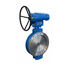
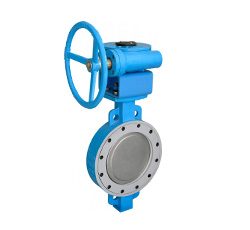
- Flange Type Double Eccentric High Performance Butterfly Valve
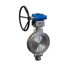
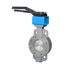
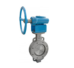
- Wafer Type Double Eccentric High Performance Butterfly Valve
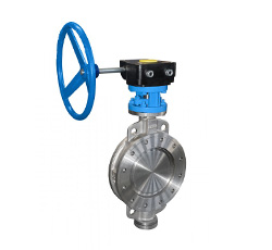
- Lug Type Double Eccentric High Performance Butterfly Valve
Contact us
Tel:+86-577-8682 5111
Email:zjbeize@163.com
Summary of Functions
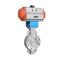
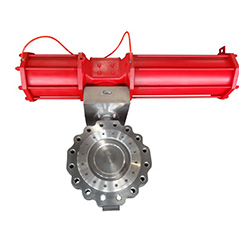
High performance butterfly valve, for the eccentric construction of the disc and the sealing ring ,the valve has a compact construction, small volume, light weight, reliable sealing, long service life and other feature, and it has both regulating and shut-off function. This kind of valve is widely used for cutting off the medium such as air ,water, sewage, oil, liquid, gas, natural gas and steam or controlling the pressure and flow in metallurgy, chemical industry, electric power, textile, food, medicine, paper and other departments of industrial, municipal engineering, water plant and other pipelines.
This series products are divided into PTFE seat and PTFE + metal seat sealing constructions, both of them are zero leakage in pressure testing. The flow characteristic of this kind of valve is approximate equal percentage.
Products Features
1. High performance regulating and shut off function, it not only can be used as regulating valve, but also can be used as shut off valve.
2. Excellent isolation function for gas and liquid and control characteristics of flow.
3. Small friction, no binding on the seat during the opening and closing, long service life.
4. The sealing ring is easy to be replaced and adjusted.
5. Small operation torque and reliable torque to shut off.
6. Fire safe type can be designed according to customers requirement.
Construction Feature
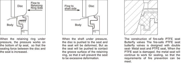
For the double eccentric construction, during the opening, the disc get away from the seat gradually, the friction between the sealing surface is reduced, so that the service life is prolonged. The seat is lip type, and the material is PTFE, RPTFE or other Ultra-high molecular weight polyethylene, so that regardless of the direction of the fluid, the seat always can return to the original position after deformation to guarantee the seal performance.
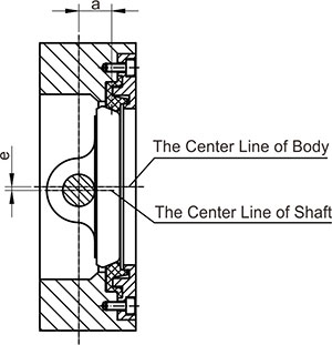
Instruction:
Eccentric 1: e- The eccentric between the center line of shaft and the center line of the body.
Eccentric 2: a- The eccentric between the center line of shaft and the center of the seat sealing surface.
- Anti-electrostatic design: As the seat is PTFE or other nonmetallic material, electrostatic will be produced during the opening and closing progress of the disc and seat , the accumulation of electrostatic will result in safety problem, so that limit sleeve is designed to transfer the electrostatic on disc to the body and as the anti-static bolt on the body keep contacting with floor, so that the electrostatic accumulation can be eliminated.
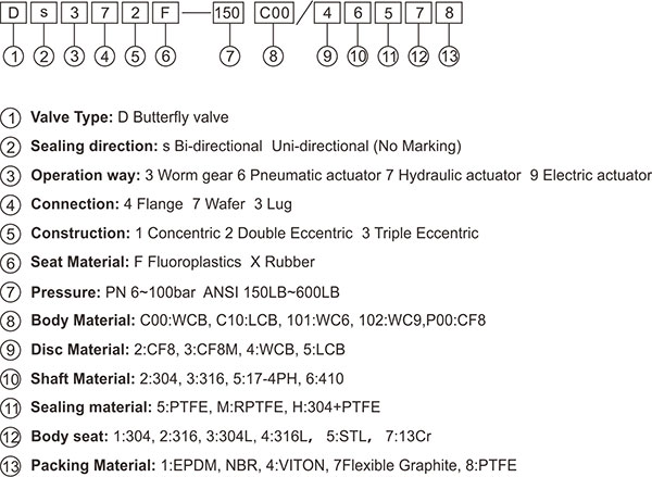
Model Designations
Standard
| Design & Manufacture | Flange Connection | Face to Face Dimension | Test & Inspection |
| GB/T12238 | GB/T 9113 | GB/T 12221 | GB/T 13927 |
| API 609 | ASME B16.5 ASME B16.47 | API 609 ASME B16.10 | API 598 |
| EN 593 | EN 1092 | EN 558 | EN 12266-1 |
| ISO 10631 | ISO 7005 | ISO 5752 | ISO 5208 |
Scope of Application
Nominal Diameter: 1-1/2" ~ 48" (DN40~1200)
Nominal Pressure: 150LB ~ 600LB (PN6~100)
Suitable Temperature: -50°C ~200°C
Connection: Wafer, Lug, Flange
Applicable Medium: fresh water, sea water, air, almost of the chemicals and all kinds of corrosive medium.
Part and Material
The Valve Explosion Figure

Part and Material
Basic Configuration of Parts and Materials
| Item No. | Part Name | Item No. |
| 1 | Screw for bottom cover | 8.8 / B7 / B8 / B8M |
| 2 | Bottom cover | A105 / 304 / 316 / 2205 |
| 3 | Gasket | 304+Graphite/ 316+Graphite/PTFE |
| 4 | Clamping ring | 1035 / 304 / 316 / 2205 |
| 5 | Lower bushing | SF-1 / SF-1S / C95200 |
| 6 | Body | WCB / CF8 / CF8M / 4A |
| 7 | Pin | 410 / 304 / 316 / F51 |
| 8 | Disc | WCB / CF8 / CF8M / 4A |
| 9 | Sealing ring | PTFE/RPTFE/PEEK/XTREME |
| 10 | Retaining ring | A105 / 304 / 316 / 2205 |
| 11 | Screws on retaining ring | 8.8 / B7 / B8 / B8M |
| 12 | Shaft | 410 / 304 / 316 / F51 |
| 13 | Upper Bushing | SF-1 / SF-1S / C95200 |
| 14 | Packing | Flexible Graphite/PTFE/Rubber |
| 15 | Packing gland | WCB / CF8 / CF8M / 4A |
| 16 | Studs for gland | 8.8 / B7 / B8 / B8M |
| 17 | Nuts for Gland | 8.8 / B7 / B8 / B8M |
| 18 | Nuts for Yoke | 8 / 2H / 8M |
| 19 | Yoke | WCB / CF8 / CF8M |
| 20 | Studs for Yoke | 8.8 / B7 / B8 / B8M |

Connection Dimensions D342F-300C 2"~24"
| NPS | L | Flange Dimensions | Overall Dimensions |
The Dimensions of Top Flange |
Weight(Kg) | |||||||||||
| D | D1 | D2 | f | b | Z-φ d | H0 | H | A | B | G | ISO 5211 | d0 | h | |||
| 2” | 150 | 165 | 127 | 92 | 2 | 23 | 8-φ19 | 82.5 | 195 | 144 | 50 | 180 | F07 | 16 | 35 | 19 |
| 2.5” | 170 | 190 | 149.2 | 105 | 2 | 26 | 8-φ22 | 95 | 210 | 144 | 50 | 180 | F07 | 16 | 35 | 20 |
| 3” | 180 | 210 | 168.3 | 127 | 2 | 29 | 8-φ22 | 105 | 215 | 144 | 50 | 180 | F07 | 18 | 40 | 23 |
| 4” | 190 | 255 | 200 | 157 | 2 | 32 | 8-φ22 | 127.5 | 235 | 144 | 50 | 180 | F07 | 18 | 40 | 26 |
| 5” | 200 | 280 | 235 | 186 | 2 | 35 | 8-φ22 | 140 | 285 | 200 | 63 | 300 | F10 | 22 | 45 | 43 |
| 6” | 210 | 320 | 270 | 216 | 2 | 37 | 12-φ22 | 215 | 315 | 230 | 80 | 350 | F12 | 30 | 60 | 64 |
| 8” | 230 | 380 | 330.2 | 270 | 2 | 42 | 12-φ25 | 220 | 370 | 230 | 80 | 350 | F12 | 35 | 70 | 74 |
| 10” | 250 | 445 | 387.4 | 324 | 2 | 48 | 16-φ29 | 270 | 415 | 260 | 125 | 400 | F14 | 40 | 80 | 119 |
| 12” | 270 | 520 | 450.8 | 381 | 2 | 51 | 16-φ32 | 310 | 470 | 260 | 125 | 400 | F14 | 45 | 90 | 165 |
| 14” | 290 | 585 | 514.4 | 413 | 2 | 54 | 20-φ32 | 330 | 525 | 260 | 125 | 400 | F16 | 50 | 100 | 259 |
| 16” | 310 | 650 | 571.5 | 470 | 2 | 58 | 20-φ35 | 385 | 585 | 290 | 160 | 500 | F25 | 60 | 120 | 325 |
| 18” | 330 | 710 | 628.6 | 533 | 2 | 61 | 24-φ35 | 410 | 620 | 418 | 200 | 600 | F25 | 70 | 130 | 366 |
| 20” | 350 | 775 | 685.8 | 584 | 2 | 64 | 24-φ35 | 425 | 692 | 418 | 200 | 600 | F25 | 70 | 130 | 444 |
| 24” | 390 | 915 | 812.8 | 692 | 2 | 70 | 24-φ41 | 480 | 815 | 510 | 263 | 700 | F30 | 90 | 160 | 661 |
Note:
1. The above dimensions are normal dimensions according to American standard, but it also can be made according to different requirements.
2. For restricted by length, for inquired specifications not listed, please contact us.
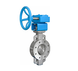
3. The operation can be Worm gear , pneumatic actuator, electric actuator and hydraulic actuator, ect.

Connection Dimensions D37A2F-600C 2"~24" D33A2F-600C 2"~24"
| NPS | L | Flange Dimensions | Overall Dimensions | The Dimensions of Top Flange | Weight(Kg) | |||||||||||
| D1 | Z-Φd | Z-W | D0 | H | A | B | C | E | G | ISO 5211 | d0 | h | Wafer | Lug | ||
| 2” | 46 | 127 | 8-Φ19 | 8-5/8-11UNC | 88 | 195 | 144 | 56 | 56 | 56 | 180 | F07 | 16 | 35 | 11 | 15 |
| 2.5” | 49 | 149.2 | 8-Φ22 | 8-3/4-10UNC | 100 | 210 | 144 | 56 | 56 | 56 | 180 | F07 | 16 | 35 | 14 | 18 |
| 3” | 54 | 168.3 | 8-Φ22 | 8-3/4-10UNC | 120 | 270 | 144 | 56 | 56 | 56 | 180 | F07 | 18 | 40 | 23 | 25 |
| 4” | 64 | 200 | 8-Φ25 | 8-7/8-10UNC | 135 | 285 | 200 | 75 | 96 | 96 | 300 | F10 | 22 | 45 | 32 | 37 |
| 5” | 78 | 235 | 8-Φ29 | 8-1-8UNC | 160 | 325 | 200 | 75 | 96 | 96 | 300 | F10 | 25 | 50 | 52 | 60 |
| 6” | 78 | 270 | 12-Φ29 | 12-1-8UNC | 190 | 360 | 230 | 90 | 120 | 120 | 350 | F12 | 30 | 60 | 85 | 119 |
| 8” | 102 | 330.2 | 12-Φ32 | 12-11/8-8UN | 225 | 430 | 260 | 152 | 165 | 165 | 400 | F14 | 40 | 80 | 102 | 126 |
| 10” | 117 | 387.4 | 16-11/4-8UN | 16-11/4-UN | 270 | 505 | 260 | 152 | 165 | 165 | 400 | F16 | 50 | 100 | 100 | 120 |
| 12” | 140 | 450.8 | 20-11/4-8UN | 20-11/4-8UN | 310 | 540 | 290 | 180 | 198 | 198 | 500 | F25 | 60 | 120 | 150 | 200 |
| 14” | 155 | 514.4 | 20-13/8-8UN | 20-13/8-8UN | 350 | 580 | 418 | 200 | 215 | 215 | 600 | F25 | 70 | 130 | 235 | 290 |
| 16” | 178 | 571.5 | 20-11/2-8UN | 20-11/2-8UN | 375 | 605 | 418 | 200 | 215 | 215 | 600 | F30 | 80 | 130 | 305 | 350 |
| 18” | 200 | 628.6 | 20-15/8-8UN | 20-15/8-8UN | 430 | 690 | 510 | 235 | 270 | 270 | 700 | F30 | 90 | 160 | 350 | 400 |
| 20” | 216 | 685.8 | 24-15/8-8UN | 24-15/8-8UN | 470 | 730 | 510 | 235 | 270 | 270 | 700 | F30 | 100 | 170 | 372 | 503 |
| 24” | 232 | 812.8 | 24-17/8-8UN | 24-17/8-8UN | 540 | 845 | 510 | 235 | 270 | 270 | 700 | F35 | 110 | 170 | 485 | 687 |
Note:
1. The above dimensions are according to API609, and the flanges dimensions are made according to ASME standard, but it also can be made according to different requirements.
2. For restricted by length, for inquired specifications not listed, please contact us.
3. The operation can be Worm gear , pneumatic actuator, electric actuator and hydraulic actuator, ect.