Products
- Products
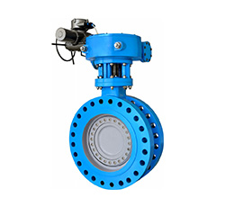
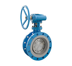
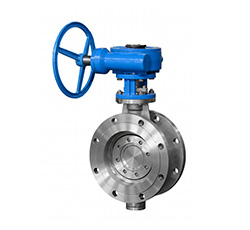
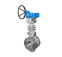
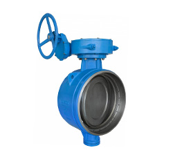
- Flange Type Triple Eccentric Metal Seal Butterfly Valve
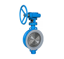
- Wafer Type Triple Eccentric Metal Seal Butterfly Valve
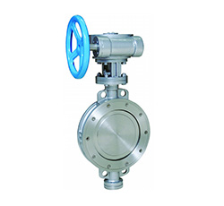
- Butt-welded Triple Eccentric Metal Seal Butterfly Valve
- API Standard Wafer Type Triple Eccentric Metal Seal Butterfly Valve
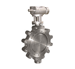
- API Standard Lug Type Triple Eccentric Metal Seal Butterfly Valve
Contact us
Tel:+86-577-8682 5111
Email:zjbeize@163.com

Summary of Functions
Triple eccentric metal seal butterfly valve designs in triple offset construction. The laminated seal or metal to metal seal makes the valve can be used for high temperature and high pressure working condition with long service life and energy saving. The triple eccentric metal seal butterfly valve is designed as a device to shut-off or regulate the working medium flow and widely installed in industrial pipelines with corrosive medium in metallurgy, iron and steel industry, power plant, petroleum, chemical industry, heat supply, inflammable gas, municipal water supply and drainage and etc.
As the latest technology achievement, triple eccentric butterfly valves provide a variety of connections to meet different face to face dimensions, such as wafer type, lug type, flanged type, ring-joint type, butt-welded type and jacketed type. It is suitable for acid, alkali and other corrosive medium at both high and low temperature due to wide material selection. Especially in large-diameter butterfly valve, it is continuously replacing the shut-off valves such as gate valve and ball valve with its advantage of zero leakage; meanwhile it is also continuously replacing the regulating valves such as globe valve with its excellent performance in regulation and control.
Products Features
1. High performance triple eccentric patented sealing system.
- Laminated seat valve :Zero leakage sealing in bi-directional (As per DIN class I or ANSI Class VI).
- Integral seat valve: Bi-directional tight sealing ( As per ANSI Class V)
2. Excellent isolation and control function for gas and liquid.
3. Welded stainless steel or stellite body seat is specially designed for long service life.
4. No friction, wear and stagnation on the seat during the opening and closing.(Compression only)
5. The seal ring is easy to be replaced and adjusted.
6. Applicable to harsh working condition such as high temperature, high pressure and corrosive conditions.
7. The metal to metal seal ring is suitable for +600°C.
8. Self-compensating for temperature variances.
9. Low operation torque and reliable shut off torque.
10. Natural fire safe design.
11. The disc sealing ring compress along the circumference uniformly just as the effect of welding, to make the seal ring bend as spring.
The resilient seal make sure the sealing performance is compliance with API 598 standard - Zero leakage for liquid or gas of the resilient
seat valves. The resiliency of the seal makes the disc remain closing tight seal in the thermal cycle just as shown in below figure.
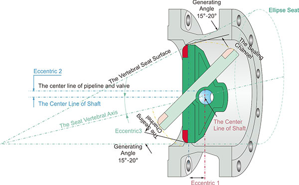
The Principe of Triple Eccentric
Eccentric 1: The shaft is placed behind the seat center line, so that the sealing ring can closely contact the whole seat.
Eccentric 2: The center line of shaft is deviated from the center line of the pipeline and valve, so that it can be avoid the interference of valve opening and closing.
Eccentric 3: Seat cone axis is deviated from the centerline of the valve shaft, so the friction can be eliminated during the closing and opening process, and realizes the uniform compression sealing around the entire seat.
Construction Feature
Laminated disc sealing
Seating force is generated by the torque during closing and works uniformly around the entire circumference. The resilient seal flexes and keeps the original shape of the valve seat. Compression force works uniformly along the circumference to realize two-way tightness shut off . The elasticity of the seal allows the valve body and disc to be contacted or expanded to avoid the risk of blockage due to temperature fluctuations. This sealing construction is able to be adjusted and aligned by itself.
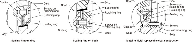
There Are Various Sealing Construction To Meet Different Requirements.
1. Normal Type: The laminated sealing ring is fixed to the disc, easy to be replaced and adjusted, suitable for most of working condition.
2. Seal on body construction: The sealing ring is fixed to the body, during the opening, the sealing ring wont move with the disc, so that the sealing ring is not easy to be damaged. When the requested face to face is short, the seal on body construction is more suitable than seal on disc construction, for the seal on disc construction, and the thickness of disc is increased, and the outside surface of disc and retaining ring will stick out from the flange sealing surface.
3. Replaceable seat type: Both the seat on body and the sealing ring on disc can be replaceable, its easy to be repaired and replaced, the maintenance cost is reduced.
Disc Sealing Ring
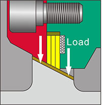
Seating force is generated by the torque during closing and works uniformly around the entire circumference. The resilient seal flexes and keeps the original shape of the valve seat. Compression force works uniformly along the circumference to realize two-way tightness shut off . The elasticity of the seal allows the valve body and disc to be contacted or expanded to avoid the risk of blockage due to temperature fluctuations. This sealing construction is able to be adjusted and aligned by itself.
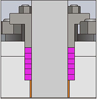
Low leakge shaft seal (0-20ppm), the polishing of shaft is 8RMS, and the polishing of the OD ( outer dia-meter ) of the stuffing box is 32 RMS. it can provide dynamic load to extend the service life without maintenance and the packing is easy to be adjusted.
Stem blow protection: In accordance with API 609 standard, double pro-tection to prevent valve shaft blow out.
Part and Material
The Valve Explosion Figure
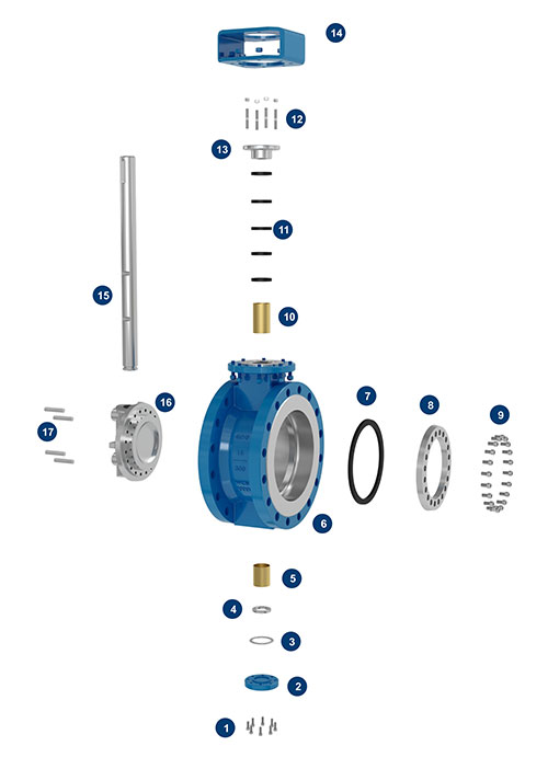
Part and Material
Basic Configuration of Parts and Materials
| Item No. | Part Name | Carbon steel | Stainless Steel | Low Temperature Steel | High Temperature Steel |
| 1 | Screw for bottom cover |
8.8/B7 | B8 | B8/L7 | B7/B8/B16 |
| 2 | Bottom cover | A105 | 304 | 304/LF2 | F11/304 |
| 3 | Gasket | 304+Graphite | 304+Graphite | 304+Graphite | 304+Graphite |
| 4 | Clamping ring | 1035 | 304 | 304 | 304 |
| 5 | Lower bushing | SF-1 | SF-1S/C95200 | SF-1S/C95200 | 304+N |
| 6 | Body | WCB | CF8 | LCB/LC1 | WC6/C5 |
| 7 | Sealing ring | 304+Graphite | 304+Graphite | 304+Graphite | 304+Graphite |
| 8 | Retaining ring | A105 | 304 | 304/LF2 | F11/304 |
| 9 | Screws on retaining ring |
8.8/B7 | B8 | B8/L7 | B7/B8/B16 |
| 10 | Upper Bushing | SF-1 | SF-1S/C95200 | SF-1S/C95200 | 304+N |
| 11 | Packing | Flexible Graphite |
Flexible Graphite |
Flexible Graphite |
Flexible Graphite |
| 12 | Studs for gland | 8.8/B7 | B8 | B8/L7 | B7/B8/B16 |
| 13 | Packing gland | WCB | CF8 | CF8/LF2 | F11/CF8 |
| 14 | Yoke | WCB | WCB/CF8 | WCB/CF8 | WCB/CF8 |
| 15 | Shaft | 410/420 | 304/17-4PH | 410/17-4PH | 304/XM-19 |
| 16 | Disc | WCB | CF8 | LCB/LC1 | WC6/C5 |
| 17 | Pin | 410/420 | 304/17-4PH | 410/17-4PH | 304/XM-19 |
Model Designations
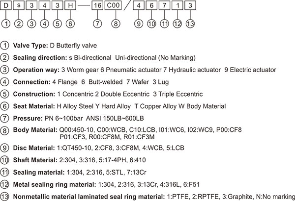
Standard
| Design & Manufacture | Flange Connection | Face to Face Dimension | Test & Inspection |
| JB/T 8527 | GB/T 9113 | GB/T 12221 | GB/T 13927 |
| API 609 | ASME B16.5 ASME B16.47 | API 609 ASME B16.10 | API 598 |
| EN 593 | EN 1092 | EN 558 | EN 12266-1 |
| ISO 10631 | ISO 7005 | ISO 5752 | ISO 5208 |
Scope of Application
Nominal Diameter: 2" ~160" (DN50~4000)
Nominal Pressure: 150LB ~ 600LB (PN10~100)
Suitable Temperature: -180°C ~700°C
Connection: Wafer, Lug, Flange, Butt-welded
Applicable Medium: fresh water, sea water, sewage, air, steam, food, pharmaceutical, oil and various kinds of Oil,
acid , alkali, salt and other weak corrosive medium, etc

Connection Dimensions D343H-25C00/46713 DN50~DN1600
|
DN |
L | Flange Dimensions | Overall Dimensions |
The Dimensions of Top Flange |
Weight(Kg) | ||||||||||||
|
D |
D1 | D2 | f | b | Z-Φd | 4-W | H0 | H | A | B | G | ISO 5211 | d0 | h | |||
| 50 | 108 | 165 | 125 | 102 | 3 | 20 | 4-Φ18 | --- | 82.5 | 195 | 50 | 144 | 180 | F07 | 16 | 35 | 17 |
| 65 | 112 | 185 | 145 | 122 | 3 | 22 | 8-Φ18 | --- | 92.5 | 215 | 50 | 144 | 180 | F07 | 16 | 35 | 18 |
| 80 | 114 | 200 | 160 | 138 | 3 | 24 | 8-Φ18 | --- | 100 | 215 | 50 | 144 | 180 | F07 | 16 | 35 | 20 |
| 100 | 127 | 235 | 190 | 162 | 3 | 24 | 8-Φ22 | --- | 117.5 | 235 | 50 | 144 | 180 | F07 | 18 | 40 | 23 |
| 125 | 140 | 270 | 220 | 188 | 3 | 26 | 8-Φ26 | --- | 135 | 290 | 63 | 200 | 300 | F10 | 22 | 45 | 38 |
| 150 | 140 | 300 | 250 | 218 | 3 | 28 | 8-Φ26 | --- | 180 | 310 | 63 | 200 | 300 | F10 | 25 | 50 | 49 |
| 200 | 152 | 360 | 310 | 278 | 3 | 30 | 8-Φ26 | 4-M24 | 185 | 370 | 80 | 230 | 350 | F12 | 30 | 60 | 64 |
| 250 | 165 | 425 | 370 | 335 | 3 | 32 | 8-Φ30 | 4-M27 | 215 | 397 | 80 | 230 | 350 | F12 | 35 | 70 | 81 |
| 300 | 178 | 485 | 430 | 395 | 4 | 34 | 12-Φ30 | 4-M27 | 250 | 455 | 125 | 260 | 400 | F14 | 40 | 80 | 144 |
| 350 | 190 | 555 | 490 | 450 | 4 | 38 | 12-Φ33 | 4-M30 | 285 | 495 | 125 | 260 | 400 | F14 | 45 | 90 | 172 |
| 400 | 216 | 620 | 550 | 505 | 4 | 40 | 12-Φ36 | 4-M33 | 330 | 535 | 125 | 260 | 400 | F16 | 50 | 100 | 272 |
| 450 | 222 | 670 | 600 | 555 | 4 | 46 | 16-Φ36 | 4-M33 | 345 | 560 | 160 | 290 | 500 | F25 | 55 | 110 | 322 |
| 500 | 229 | 730 | 660 | 615 | 4 | 48 | 16-Φ36 | 4-M33 | 390 | 620 | 160 | 290 | 500 | F25 | 60 | 120 | 370 |
| 600 | 267 | 845 | 770 | 720 | 5 | 58 | 16-Φ39 | 4-M36 | 445 | 685 | 200 | 418 | 600 | F25 | 70 | 130 | 571 |
| 700 | 292 | 960 | 875 | 820 | 5 | 50 | 20-Φ42 | 4-M39 | 545 | 750 | 263 | 510 | 700 | F30 | 90 | 160 | 808 |
| 800 | 318 | 1085 | 990 | 930 | 5 | 54 | 20-Φ48 | 4-M45 | 625 | 870 | 263 | 510 | 700 | F30 | 100 | 170 | 1288 |
| 900 | 330 | 1185 | 1090 | 1030 | 5 | 58 | 24-Φ48 | 4-M45 | 685 | 965 | 263 | 510 | 700 | F35 | 110 | 170 | 1519 |
| 1000 | 410 | 1320 | 1210 | 1140 | 5 | 62 | 24-Φ56 | 4-M52 | 755 | 1040 | 333 | 550 | 800 | F35 | 120 | 190 | 1787 |
| 1200 | 470 | 1530 | 1420 | 1350 | 5 | 70 | 28-Φ56 | 4-M52 | 860 | 1180 | 333 | 550 | 800 | F35 | 140 | 200 | 2510 |
| 1400 | 530 | 1755 | 1640 | 1560 | 5 | 76 | 32-Φ62 | 4-M56 | 1020 | 1365 | 374 | 590 | 900 | F40 | 160 | 220 | 3203 |
| 1600 | 600 | 1975 | 1860 | 1780 | 5 | 84 | 36-Φ62 | 4-M56 | 1190 | 1580 | 374 | 590 | 900 | F48 | 180 | 230 | 4025 |
Note:
1. The above dimensions are normal data, and the flange dimensions are made according to EN1092-1, but it also can be made according to different requirements.
2. For restricted by length, for inquired specifications not listed, please contact us.
3. The operation can be Worm gear , pneumatic actuator, electric actuator and hydraulic actuator, ect.

| DN | L | Flange Dimensions | Overall Dimensions |
The Dimensions of Top Flange |
Weight(Kg) | ||||||||||
| D1 | D2 | ZΦ d(W) | D0 | H | A | B | C | E | G | ISO 5211 | d0 | h | |||
| 80 | 64 | 180 | 138 | 8-Φ26(M24) | 120 | 270 | 144 | 56 | 56 | 50 | 180 | F07 | 18 | 40 | 23 |
| 100 | 64 | 210 | 162 | 8-Φ30(M27) | 135 | 285 | 200 | 75 | 96 | 63 | 300 | F10 | 25 | 50 | 26 |
| 125 | 70 | 250 | 188 | 8-Φ33(M30) | 160 | 325 | 230 | 90 | 120 | 80 | 350 | F12 | 30 | 60 | 38 |
| 150 | 78 | 290 | 218 | 12-M30 | 215 | 410 | 230 | 90 | 120 | 80 | 350 | F12 | 35 | 70 | 56 |
| 200 | 102 | 360 | 285 | 12-M33 | 220 | 425 | 260 | 152 | 165 | 125 | 400 | F14 | 45 | 90 | 96 |
| 250 | 117 | 430 | 345 | 12-M36 | 265 | 505 | 260 | 152 | 165 | 125 | 400 | F16 | 50 | 100 | 130 |
| 300 | 140 | 500 | 410 | 16-M39 | 295 | 545 | 290 | 180 | 198 | 160 | 500 | F25 | 60 | 120 | 227 |
| 350 | 155 | 560 | 465 | 16-M45 | 335 | 570 | 418 | 200 | 215 | 200 | 600 | F25 | 70 | 130 | 290 |
| 400 | 178 | 620 | 535 | 16-M45 | 390 | 620 | 418 | 200 | 215 | 200 | 600 | F30 | 80 | 130 | 367 |
| 500 | 216 | 760 | 615 | 20-M52 | 450 | 760 | 510 | 235 | 270 | 263 | 700 | F30 | 100 | 160 | 476 |
| 600 | 232 | 875 | 735 | 20-M56 | 550 | 850 | 550 | 275 | 335 | 333 | 800 | F35 | 120 | 190 | 659 |
Note:
1. The above dimensions are normal data, and the flange dimensions are made according to EN1092-1, but it also can be made according to different requirements.
2. For restricted by length, for inquired specifications not listed, please contact us.
3. The operation can be Worm gear , pneumatic actuator, electric actuator and hydraulic actuator, ect.

Connection Dimensions D363H-40C00/46713 DN80~DN900 D363H-300C00/46713 3”~36”
| DN | NPS | L |
Dimensions of But-welded |
Overall Dimensions |
The Dimensions of Top Flange |
Weight(kg) | |||||||
| Dn | D1 | H0 | H | A | B | G | ISO 5211 | d0 | h | ||||
| 80 | 3” | 180 | 78 | 91 | 85 | 225 | 50 | 144 | 180 | F07 | 18 | 40 | 21 |
| 100 | 4” | 190 | 102 | 117 | 100 | 245 | 50 | 144 | 180 | F07 | 18 | 40 | 24 |
| 125 | 5” | 200 | 128 | 144 | 170 | 290 | 63 | 200 | 300 | F10 | 22 | 45 | 40 |
| 150 | 6” | 210 | 154 | 172 | 180 | 310 | 80 | 230 | 350 | F12 | 30 | 60 | 59 |
| 200 | 8” | 230 | 203 | 223 | 205 | 360 | 80 | 230 | 350 | F12 | 35 | 70 | 68 |
| 250 | 10” | 250 | 255 | 278 | 235 | 395 | 125 | 260 | 400 | F14 | 40 | 80 | 111 |
| 300 | 12” | 270 | 305 | 329 | 265 | 425 | 125 | 260 | 400 | F14 | 45 | 90 | 153 |
| 350 | 14” | 290 | 337 | 362 | 305 | 475 | 125 | 260 | 400 | F16 | 50 | 100 | 243 |
| 400 | 16” | 310 | 387 | 413 | 340 | 620 | 160 | 290 | 500 | F25 | 60 | 120 | 303 |
| 450 | 18” | 330 | 438 | 464 | 390 | 645 | 200 | 418 | 600 | F25 | 70 | 130 | 340 |
| 500 | 20” | 350 | 489 | 516 | 415 | 670 | 200 | 418 | 600 | F25 | 70 | 130 | 412 |
| 600 | 24” | 390 | 591 | 619 | 500 | 740 | 263 | 510 | 700 | F30 | 90 | 160 | 607 |
| 700 | 28” | 430 | 686 | 721 | 580 | 900 | 263 | 510 | 700 | F30 | 110 | 170 | 1013 |
| 800 | 32” | 470 | 787 | 825 | 665 | 975 | 333 | 550 | 800 | F35 | 130 | 200 | 1370 |
| 900 | 36” | 510 | 889 | 927 | 690 | 1010 | 333 | 550 | 800 | F35 | 140 | 200 | 1674 |
Note:
1. The above dimensions are normal data, and the dimensions of butt-welded end are made according to EN 12627, but it also can be made according to different requirements.
2. For restricted by length, for inquired specifications not listed, please contact us.
3. The operation can be Worm gear , pneumatic actuator, electric actuator and hydraulic actuator, ect.

Connection Dimensions D37A3H-300C 2"~48" D33A3H-300C 2"~48"
| NPS | L | Flange Dimensions | Overall Dimensions | The Dimensions of Top Flange | Weight(Kg) | |||||||||||
| D1 | Z-Φd | Z-W | D0 | H | A | B | C | E | G | ISO 5211 | d0 | h | Wafer | Lug | ||
| 2” | 43 | 127 | 8-Φ19 | 8-5/8-11UNC | 65 | 195 | 144 | 56 | 56 | 50 | 180 | F07 | 16 | 35 | 9 | 10 |
| 2.5” | 46 | 149.2 | 8-Φ22 | 8-3/4-10UNC | 75 | 210 | 144 | 56 | 56 | 50 | 180 | F07 | 16 | 35 | 11 | 15 |
| 3” | 48 | 168.3 | 8-Φ22 | 8-3/4-10UNC | 105 | 215 | 144 | 56 | 56 | 50 | 180 | F07 | 18 | 40 | 14 | 18 |
| 4” | 54 | 200 | 8-Φ22 | 8-3/4-10UNC | 120 | 235 | 144 | 56 | 56 | 50 | 180 | F07 | 18 | 40 | 17 | 22 |
| 5” | 59 | 235 | 8-Φ22 | 8-3/4-10UNC | 130 | 285 | 200 | 75 | 96 | 63 | 300 | F10 | 22 | 45 | 28 | 38 |
| 6” | 59 | 270 | 12-Φ22 | 12-3/4-10UNC | 190 | 315 | 230 | 90 | 120 | 80 | 350 | F12 | 30 | 60 | 30 | 42 |
| 8” | 73 | 330.2 | 12-Φ25 | 12-7/8-9UNC | 220 | 370 | 230 | 90 | 120 | 80 | 350 | F12 | 35 | 70 | 44 | 67 |
| 10” | 83 | 387.4 | 16-1-8UNC | 16-1-8UNC | 270 | 415 | 260 | 152 | 165 | 125 | 400 | F14 | 40 | 80 | 70 | 93 |
| 12” | 92 | 450.8 | 16-11/8-8UN | 16-11/8-UN | 310 | 470 | 260 | 152 | 165 | 125 | 400 | F14 | 45 | 90 | 115 | 160 |
| 14” | 117 | 514.4 | 20-11/8-8UN | 20-11/8-8UN | 330 | 525 | 260 | 152 | 165 | 125 | 400 | F16 | 50 | 100 | 208 | 285 |
| 16” | 133 | 571.5 | 20-11/4-8UN | 20-11/4-8UN | 385 | 585 | 290 | 180 | 198 | 160 | 500 | F25 | 60 | 120 | 305 | 272 |
| 18” | 149 | 628.6 | 24-11/4-8UN | 24-11/4-8UN | 410 | 620 | 418 | 200 | 215 | 200 | 600 | F25 | 70 | 130 | 341 | 360 |
| 20” | 159 | 685.8 | 24-11/4-8UN | 24-11/4-8UN | 425 | 692 | 418 | 200 | 215 | 200 | 600 | F25 | 70 | 130 | 432 | 460 |
| 24” | 181 | 812.8 | 24-11/2-8UN | 24-11/2-8UN | 480 | 815 | 510 | 235 | 270 | 263 | 700 | F30 | 90 | 160 | 465 | 624 |
| 28” | 229 | 939.8 | 28-15/8-8UN | 28-15/8-8UN | 570 | 860 | 510 | 235 | 270 | 263 | 700 | F30 | 110 | 170 | 679 | 812 |
| 32” | 241 | 1054 | 28-17/8-8UN | 28-17/8-8UN | 660 | 965 | 550 | 275 | 335 | 333 | 800 | F35 | 130 | 200 | 817 | 1010 |
| 36” | 241 | 1168.4 | 32-2-8UN | 32-2-8UN | 725 | 1025 | 550 | 275 | 335 | 333 | 800 | F35 | 140 | 200 | 1133 | 1337 |
| 40” | 300 | 1155.7 | 32-15/8-8UN | 32-15/8-8UN | 770 | 1075 | 550 | 275 | 335 | 333 | 800 | F40 | 150 | 200 | 1744 | 2058 |
| 48” | 350 | 1371.6 | 32-17/8-8UN | 32-17/8-8UN | 920 | 1295 | 590 | 320 | 360 | 374 | 900 | F40 | 170 | 220 | 2328 | 2747 |
Note:
1. The above dimensions are according to API609, and the flanges dimensions are made according to ASME standard, but it also can be made according to different requirements.
2. For restricted by length, for inquired specifications not listed, please contact us.
3. The operation can be Worm gear , pneumatic actuator, electric actuator and hydraulic actuator, ect.
Connection Dimensions D37A3H-150C 2"~56" D33A3H-150C 2"~56"
| NPS | L | Flange Dimensions | Overall Dimensions | The Dimensions of Top Flange | Weight(Kg) | |||||||||||
| D1 | Z-Φd | Z-W | D0 | H | A | B | C | E | G | ISO 5211 | d0 | h | Wafer | Lug | ||
| 2” | 43 | 120.7 | 4-Φ19 | 4-5/8-11UNC | 65 | 195 | 144 | 56 | 56 | 50 | 180 | F07 | 16 | 35 | 5 | 6 |
| 2.5” | 46 | 139.7 | 4-Φ19 | 4-5/8-11UNC | 75 | 210 | 144 | 56 | 56 | 50 | 180 | F07 | 16 | 35 | 8 | 9 |
| 3” | 48 | 152.4 | 4-Φ19 | 4-5/8-11UNC | 105 | 215 | 144 | 56 | 56 | 50 | 180 | F07 | 16 | 35 | 10 | 11 |
| 4” | 54 | 190.5 | 8-Φ19 | 8-5/8-11UNC | 120 | 235 | 144 | 56 | 56 | 50 | 180 | F07 | 18 | 40 | 13 | 15 |
| 5” | 57 | 216 | 8-Φ22 | 8-3/4-10UNC | 130 | 285 | 200 | 75 | 96 | 63 | 300 | F10 | 22 | 45 | 23 | 25 |
| 6” | 57 | 241.3 | 8-Φ22 | 8-3/4-10UNC | 170 | 300 | 200 | 75 | 96 | 63 | 300 | F10 | 25 | 50 | 25 | 30 |
| 8” | 64 | 298.5 | 8-Φ22 | 8-3/4-10UNC | 200 | 340 | 230 | 90 | 120 | 80 | 350 | F12 | 30 | 60 | 33 | 38 |
| 10” | 71 | 362 | 12-Φ25 | 12-7/8-9UNC | 240 | 380 | 230 | 90 | 120 | 80 | 350 | F12 | 35 | 70 | 50 | 66 |
| 12” | 81 | 431.8 | 12-Φ25 | 12-7/8-9UNC | 285 | 425 | 260 | 152 | 165 | 125 | 400 | F14 | 40 | 80 | 67 | 90 |
| 14” | 92 | 476.3 | 12-1-8UNC | 12-1-8UNC | 320 | 505 | 260 | 152 | 165 | 125 | 400 | F14 | 45 | 90 | 130 | 140 |
| 16” | 102 | 539.8 | 16-1-8UNC | 16-1-8UNC | 360 | 510 | 260 | 152 | 165 | 125 | 400 | F16 | 50 | 100 | 140 | 170 |
| 18” | 114 | 578 | 16-11/8-8UN | 16-11/8-8UN | 385 | 565 | 260 | 152 | 165 | 125 | 400 | F16 | 50 | 100 | 188 | 225 |
| 20” | 127 | 635 | 20-11/8-8UN | 20-11/8-8UN | 410 | 590 | 290 | 180 | 198 | 160 | 500 | F25 | 55 | 110 | 270 | 287 |
| 24” | 154 | 749.3 | 20-11/4-8UN | 20-11/4-8UN | 454 | 685 | 418 | 200 | 215 | 200 | 600 | F25 | 70 | 130 | 310 | 390 |
| 28” | 165 | 863.6 | 28-11/4-8UN | 28-11/4-8UN | 545 | 755 | 418 | 200 | 215 | 200 | 600 | F30 | 80 | 130 | 430 | 508 |
| 32” | 190 | 977.6 | 28-11/2-8UN | 28-11/2-8UN | 575 | 825 | 510 | 235 | 270 | 263 | 700 | F30 | 90 | 160 | 535 | 632 |
| 36” | 203 | 1085.8 | 32-11/2-8UN | 32-11/2-8UN | 655 | 960 | 510 | 235 | 270 | 263 | 700 | F30 | 100 | 170 | 708 | 836 |
| 40” | 216 | 1200.2 | 36-11/2-8UN | 36-11/2-8UN | 725 | 1015 | 510 | 235 | 270 | 263 | 700 | F35 | 110 | 170 | 1090 | 1286 |
| 48” | 254 | 1422.4 | 44-11/2-8UN | 44-11/2-8UN | 860 | 1150 | 550 | 275 | 335 | 333 | 800 | F35 | 130 | 200 | 1455 | 1717 |
| 56” | 279 | 1651 | 48-13/4-8UN | 48-13/4-8UN | 995 | 1345 | 550 | 275 | 335 | 333 | 800 | F40 | 150 | 200 | 1750 | 2065 |
Note:
1. The above dimensions are according to API609, and the flanges dimensions are made according to ASME standard, but it also can be made according to different requirements.
2. For restricted by length, for inquired specifications not listed, please contact us.
3. The operation can be Worm gear , pneumatic actuator, electric actuator and hydraulic actuator, ect.